MG995 Servo Motor
MG995 is a servo motor that is popular for its performance and low price. The motor is used in many applications mainly being robotics and drones.
MG995 Servo Motor Pinout Configuration
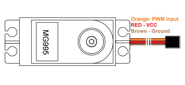
MG995 has three terminals as mentioned in pin diagram and the function of each pin is given below.
|
Pin |
Name |
Function |
|
1 |
Signal pin (Orange pin) |
The PWM signal which states the axis position is given through this pin. |
|
2 |
VCC (Red pin) |
Positive power supply for servo motor is given to this pin. |
|
3 |
Ground(Brown pin) |
This pin is connected to ground of circuit or power supply. |
MG995 Features and Electrical characteristics
- Metal geared servo for more life
- Stable and shock proof double ball bearing design
- High speed rotation for quick response
- Fast control response
- Constant torque throughout the servo travel range
- Excellent holding power
- Weight: 55 g
- Dimension: 40.7×19.7×42.9mm
- Operating voltage range: 4.8 V to 7.2 V
- Stall torque: 9.4kg/cm (4.8v); 11kg/cm (6v)
- Operating speed: 0.2 s/60º (4.8 V), 0.16 s/60º (6 V)
- Rotational degree: 180º
- Dead band width: 5 μs
- Operating temperature range: 0ºC to +55ºC
- Current draw at idle: 10mA
- No load operating current draw: 170mA
- Current at maximum load: 1200mA
Similar Servo Motors
MG995 Servo Motor Overview
Since MG995 is a servo motor providing precise rotation over 180º range its applications are many and in them a few are stated below
- The servo is suited for designing robotic arm in which wear and tear of motor is high. Being metal geared, the servo has long life and can be installed on system like robotic arm were motor work is huge.
- The servo is also suited to be used in drones and toy planes. Having a satisfying torque which is enough to overcome air resistance and control wings of plane, the servo is preferred in toy planes and drones which need precision control no matter the condition.
How to use MG995 Servo Motor
First let us consider the circuit connection of servo as shown below. Here the Red wire is connected to +5V regulated power which can deliver current up to 1Amp, Brown wire is grounded and Orange wire is connected to PWM (Pulse Width modulation) output of a microcontroller. In the circuit if microcontroller and servo has different power sources then the microcontroller ground needed to be connected to servo ground.

Now for controlling of servo there are only two important things to remember:
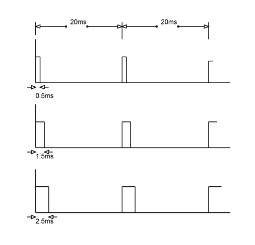
- Frequency of PWM: MG995 takes in PWM signal of frequency 50Hz and any higher and lower frequency PWM will lead to error. As shown in figure the every single cycle of PWM needs to be 20ms width for 50Hz frequency.
- Duty cycle of PWM: The duty cycle of PWM (or ratio of ON time to total cycle time) determines the position of servo axis. If we provide a PWM signal of 0.5ms ON time over 20mS complete cycle, the servo axis will move to 0º.
And if we provide a PWM signal of 1.5ms ON time over 20mS complete cycle, the servo axis will move to 90º. At last if we provide a PWM signal of 2.5ms ON time over 20mS complete cycle, the servo axis will move to 180º.
Based on these standard values we can also calculate any other degree of rotation. After calculation we just have to adjust the duty cycle of the PWM for the servo to read the signal and change to that stated position.

In this way we can control the servo position using PWM signal of any microcontroller or processor. In arduino and other development boards we will have libraries readily available to make it even easier to control the servo. If we use those libraries we can directly state the servo position instead of adjusting the PWM duty cycle every single time.
Applications
- Drones and RC planes
- Security camera
- Robotics
- Solar tracking and positioning
- Door lock and safe locks
- Hobby projects
2D-Model
All dimensions are in millimeter


