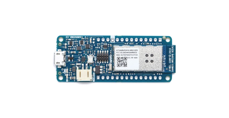
Arduino MKR1000 Wi-Fi Board
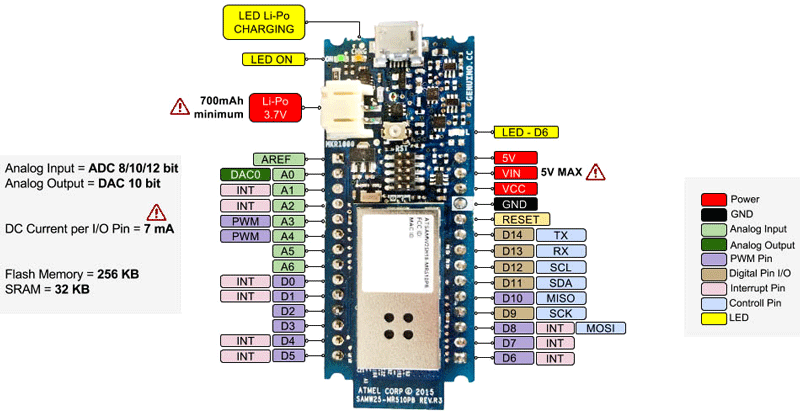
Arduino MKR1000 Pinout Description
|
Pin Category |
Pin Name |
Details |
|
Power |
Li-Po(3.7v),Vin, Vcc, 5V, GND |
Lip-Po(3.7V): The board can be powered by connecting a lithium polymer battery to this pin. The battery should have a nominal voltage of 3.7V and minimum of 700mAh Vin: The board can also be powered by a regulated 5V supply connected to this input pin. The maximum voltage for this pin is 6V 5V: If powered though USB then this output pin can be used to get a +5V supply for powering other circuit Vcc: This pin outputs a regulated 3.3V by using the on board regulator IC. GND: Ground pins. |
|
Reset |
Reset |
Resets the microcontroller. |
|
Analog Pins |
A0 – A6 |
These 7 pins are used to measure analog voltage in the range of 0-3.3V, with a resolution of 8/10/12 bit |
|
DAC Pin |
DAC0 |
Provides an analog voltage based in the digital input with a resolution of 10 bit |
|
Input/Output Pins |
Digital Pins D0 - D14 |
Can be used as input or output pins. 0V (low) and 3.3V (high) |
|
Serial |
Rx, Tx |
Used to receive and transmit TTL serial data. |
|
External Interrupts |
0, 1, 4, 5, 6, 7, 8, A1 -or 16-, A2 - or 17 |
These 8 pins can be used as an external interrupt |
|
PWM |
0, 1, 2, 3, 4, 5, 6, 7, 8, 10, A3 - or 18 -, A4 -or 19 |
The 12 pins can be used to provide 8-bit PWM. |
|
SPI |
10(MOSI), 12 (MISO) and 9 (SCK) |
Used for SPI communication. |
|
Inbuilt LED |
13 |
To turn on the inbuilt LED. |
|
IIC |
11 (SDA), 12 (SCL) |
Used for I2C/TWI communication. |
|
AREF |
AREF |
To provide reference voltage for input voltage. |
Arduino MKR1000 Technical Specifications
|
Microcontroller |
SAMD21 Cortex-M0+ 32bit low power ARM MCU |
|
Operating Voltage |
3.3V |
|
Recommended Input Voltage for Vin pin |
Regulated 5V |
|
Analog Input Pins |
7 (A0 – A6) |
|
Digital I/O Pins |
8 |
|
DC Current on I/O Pins |
7 mA |
|
DC Current on 3.3V Pin |
50 mA |
|
Flash Memory |
256 KB |
|
SRAM |
32 KB |
|
EEPROM |
no |
|
Frequency (Clock Speed) |
32.768 kHz (RTC), 48 MHz |
|
Communication |
IIC, SPI, USART |
Other Arduino Boards
Arduino UNO, Arduino Pro Mini, Arduino Mega, Arduino Due, Arduino Leonardo
Other Development Boards
Raspberry Pi, PIC Development Board, AVR Development Board, MSP430 Launchpad, Intel Edison, ESP32
Other IoT Development Boards
Raspberry Pi, ESP8266, ESP12, ESP32, Intel Edison, Arduino Yun, NodeMCU, BLE, LoRa, NRF24L01
Difference between ESP8266 and Arduino MKR1000
Ever since the launch of the ESP8266 module which is a part of the NodeMCU series, it has been increasingly used in most of the IoT projects. The popularity of the device is due to its cheap price and its ability to be programmed using Arduino IDE. Now considering the price and functionality of an Arduino MKR100 Wi-Fi board, it is often confusing to select an ESP8266 over a MKR1000.
Comparing the specs and functionality of both the boards, it is obvious that the MKR1000 stands high with more digital pins, Li-Po battery charging circuit option, DAC option, high programming memory and an Encryption chip. But the two considerable downsides are that MKR1000 is at least 8 times costlier than ESP8266 and does not have a strong community support. So it purely depends on the designer to consider the pros and cons and select make his ideal choice.
Understanding Arduino MKR1000
The Arduino MKR1000 stands for “Maker 1000”. This small form factored board by Arduino is aimed at building IoT projects since it comes with an on-board Wi-Fi feature. It also runs on 32-bit architecture making it faster and more reliable with encryption features. As always since the board is from Arduino, it is expected to have a huge community support and will be easier for beginners to get started with IoT projects with less experience on networking.
Powering your Arduino MKR1000
There are totally three ways by which you can power your Nano.
Li-Po battery Connector: The board comes with a lithium polymer battery connector and the circuit associated with it to charge the battery. So once you development is done, you can run the module on a battery by just connecting it to this connector and charging through USB.
USB Jack: Connect the mini USB jack to a phone charger or computer through a cable and it will draw power required for the board to function. The board works on 3.3V so the 5V from the USB will be regulated to 3.3V using the on-board regulator.
Vin Pin: The Vin pin can be supplied with a regulated +5V to power the board.
Vcc Pin: If you have a regulated +3.3V supply, then you can directly provide this to the Vcc pin of the Arduino.
Input/output:
There are totally 15 digital Pins and 7 Analog pins on your MKR1000 board. These entire pins are only 3.3V compatible. The digital pins can be used to interface sensors by using them as input pins or drive loads by using them as output pins. A simple function like pinMode() and digitalWrite() can be used to control their operation. The operating voltage is 0V and 3.3VV for digital pins. The analog pins can measure analog voltage from 0V to 3.3V using any of the 7 Analog pins using a simple function like analogRead().
These pins apart from serving their purpose, can also be used for special purposes, which are discussed below:
- Serial Pins 13 (Rx) and 14 (Tx): Rx and Tx pins are used to receive and transmit TTL serial data.
- External Interrupt Pins: These pins can be configured to trigger an interrupt on a low value, a rising or falling edge, or a change in value.
- PWM Pins: These pins provide an 8-bit PWM output by using analogWrite() function.
- SPI Pins: These pins are used for SPI communication.
- In-built LED Pin D6: This pin is connected with a built-in LED, when pin 6 is HIGH – LED is on and when pin 6 is LOW, its off.
- I2C Pins: Used for IIC communication using Wire library.
- AREF: Used to provide reference voltage for analog inputs with analogReference() function.
- Reset Pin: Making this pin LOW, resets the microcontroller.
How to use Arduino MKR1000
It will hardly take 5-10 minutes to upload your first program to Arduino MKR1000. All you need the Arduino IDE, an USB cable and your board itself.
Download and Install Arduino:
The first step would be to install the Arduino IDE which is available for download for free from the below link. After installing Arduino, you might also want to install the drivers (link given below) for you Arduino to communicate with your Computer. Make sure you get the latest version (1.6.8 or above) of the Arduino IDE.
Install board package and upload the program:
By the time I am writing this article the Arduino IDE by default does not have the MKR1000 board included in the Tools boards menu. So you have to open the board manager and install the board details for the MKR1000 board. More guidance can be found here.
Once installed, just connect you board to the computer through the USB cable and then you can select the required board and COM port. Then upload any sample program to check if the board is working as expected from here you can use the internet to build tons of amazing projects and have fun.
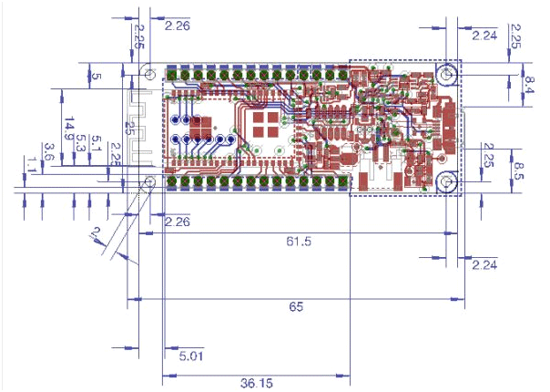
2D-Model and Dimensions