MSP430 Launchpad
MSP430 Launchpad is a hardware development tool for the MSP430 Value Line series of microcontrollers and is popular among hobbyists for its low cost and features. It is an easy way to start developing on the MSP430 MCUs, with on-board emulation for programming and debugging as well as buttons and LEDs for a simple user interface.
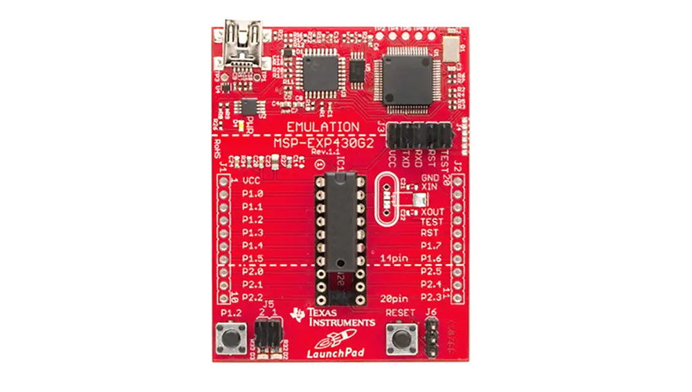
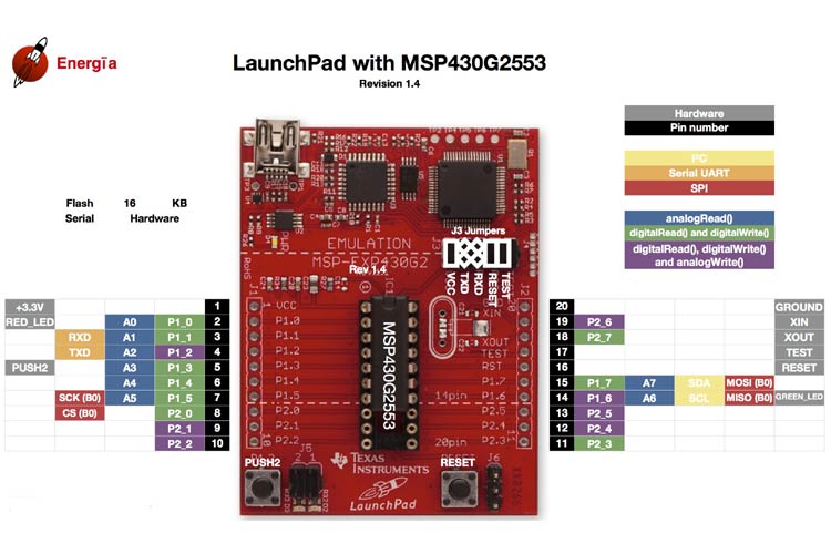
MSP430 Pinout Configuration
There are few ports present on the board as shown in the MSP430 pinout and the functions of these ports are described below:
|
Name |
Pin |
Function |
|
GPIO pins
|
P1.0 to P1.7 & P2.0 to P2.5 |
These are the input/output pins of the microcontroller (placed in the socket) given out of the board for interfacing. |
|
Button |
P1.3 |
Can be used for general purpose interfacing during operation. |
|
LEDs |
P1.0 & P1.6 |
Can be used for general purpose indication during operation. |
|
Reset |
Connected to RESET pin of microcontroller |
If pressed, the microcontroller will reset. |
|
Power Connected |
Three pin jack at the bottom |
Can be used to connect eternal power sources after programming. |
|
Crystal pads |
Solder joints adjacent to controller |
A crystal oscillator can be soldered here for providing more accurate clock source. |
|
eZ430 connector |
Six pin connector |
Provides a bridge between Emulator board and Microcontroller breakout board. Can be disconnected to isolate both sections of the PCB. |
|
Programming port |
USB connector at the top |
The device will be connected to PC (For programming and power) using this port. |
Features and Electrical Characteristics
- Dip socket for easy plug-in or removal of microcontroller
- Energy trace technology available for ultra-low-power debugging
- One button and two LEDs for user interaction
- USB debugging and programming interface featuring a driverless installation
- Available UART serial communication with up to 9600 Baud
- Supports MSP430G2xx2, MSP430G2xx3, and MSP430F20xx devices in PDIP14 or PDIP20 packages
- Hardware reset button available on board
- Operating voltage range: 5V
Note: More technical information can be found in the MSP430 Datasheet, linked at the bottom of this page.
The MSP430 board can be used for programming many controllers, but there will be two microcontrollers available with the development board, so we will mention features of them below:
|
Feature |
MSP430G2553 Controller |
MSP430G2452 Controller |
|
CPU architecture |
16-Bit RISC Architecture |
16-Bit RISC Architecture |
|
Frequency of Operation |
Up to 16MHz |
Up to 16MHz |
|
Flash Memory |
16KBytes |
8KBytes |
|
RAM |
512Bytes |
256Bytes |
|
Interface |
1x I2C 1x SPI 1x UART |
1x I2C 1x SPI
|
|
Programmable I/O pins |
16 |
16 |
|
ADC |
8 channel of 10 bit resolution |
8 Channel of 10 bit resolution |
|
Comparator |
8 input available |
8 input available |
|
Timer |
2 x 16 bit |
1 x 16 bit |
|
Capacitive touch interface |
Available |
Available |
|
Internal temperature sensor |
Available |
Available |
|
Watchdog timer |
Available |
Available |
Similar MCU Boards
CC1352P, CC1352R, CC26x2R, CC3200
MSP430 Launchpad Overview
MSP430 launchpad is a development board which can be used to design all Arduino based applications since both have similar capabilities and features. Similar to Arduino being developed on AVR controllers, the MSP430 launchpad is developed on TI MSP430 microcontrollers. This device can be used to develop low-end applications and not high-end applications, as it does not have high processing power like Raspberry pi.
How to use MSP430 Launchpad
Similar to Arduino, we need IDE software for interfacing the board to PC and programming the microcontroller seated in it. There are two IDE software available for the MSP430 launchpad and the link of both are given below:
In both IDE using energia is easier, as the software is developed based on arduino IDE and they share similar programming feel. So for those who are familiar with arduino will fell energia IDE similar and helpful.
Once you download the IDE software, install it in your PC and do it with administer rights for avoiding future troubles. Run the installed program and connect the development board to the PC using the cable provided along with the kit. The PC will detect the board automatically after connecting. Once detection in done, go to the example programs in the IDE and choose blinking program to execute. Once it is done, the IDE will debug the blinky program for error and after successful compilation, the program will be transferred to microcontroller in the board. Once the program is transferred, the microcontroller executes the blinky program saved in its flash memory and we will see the LED present on the board blinking.
So with that, we have successfully programmed the controller via usb interface and in the similar way, we can write the other programs in the IDE and dump these programs in the controller after compilation.
Applications
- TI microcontroller learning tool
- Prototyping
- Robotics
- Planes and Drones
- Building automation
- Access control and security
- Security systems and electronic locks
- Electronic and Electrical measuring instruments
- Health monitoring devices
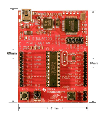
2D Model and Dimensions