ADS1115 Ultra-Small, Low-Power, 16-Bit Analog-to-Digital Converter IC
ADS1115 IC is a 16-Bit ADC with Internal Reference, Oscillator, 860-SPS, and Programmable Comparator which is ultra-small, low-power, and I2C compatible. In simple terms, the ADS1115 is a 16-bit ADC with four inputs that are multiplexed. This IC is from Texas Instruments; a low-drift voltage reference and an oscillator are included in the ADS1115 IC. A programmable gain amplifier (PGA) and a digital comparator are also included in the ADS1115 SMD IC.
ADS1115 is one of the most powerful and versatile Analog to Digital Converter (ADC). A lot of microcontrollers (like the Arduino boards, ESP8266 boards) have built-in ADCs and it’s very essential because most sensors give analog output whereas microcontrollers need digital input. Sometimes these built-in ADCs don’t suffice the need (they have lesser gain and poor resolution) hence ADS1115 type of compact ADC boards come in handy. Let’s do a little comparison between Arduino and ADS1115 to understand how powerful ADS1115 ADC is; Arduino has a 10-bit ADC which means it can hold a digital value of 0 to 1023 (because 210 is 1024) whereas the 16-bit ADS1115 can hold 216 which is 65536. Hence, ADS1115 can give a better resolution, which means, ADS1115 can give finer values and it can be more accurate. It also features PGA (Programmable Gain Amplifier), using which we can measure very low voltages like millivolts by programming the amplifier to multiply with a gain value so the measurement is accurate.
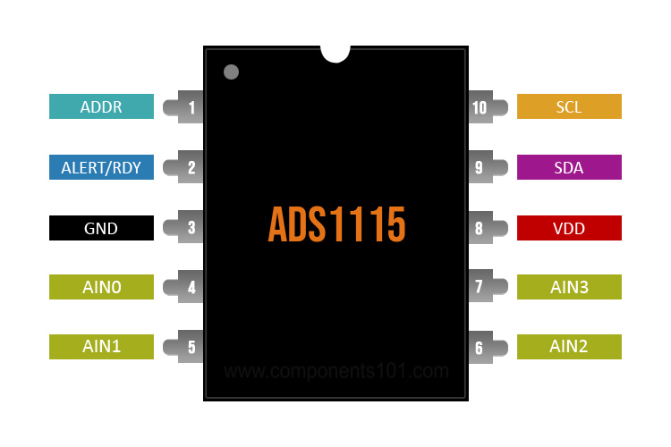
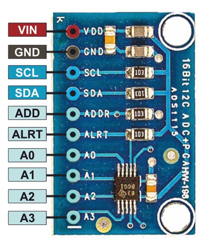
ADS1115 Pinout Configuration
|
Pin Name |
Pin Description |
|
ADDR |
I2C address select (slave) |
|
ALERT/RDY |
Digital comparator output or conversion ready |
|
GND |
Ground |
|
AIN0 |
Differential channel 1: Single-ended channel 1 input or Negative input |
|
AIN1 |
Differential channel 1: Single-ended channel 2 input or Negative input |
|
AIN2 |
Differential channel 2: Single-ended channel 3 input or Positive input |
|
AIN3 |
Differential channel 2: Single-ended channel 4 input or Negative input |
|
VDD |
Power supply: 2.0V to 5.5V |
|
SDA |
Serial data: Transmits and receives data (used for I2C communication) |
|
SCL |
Serial clock input: Clocks data on SDA (used for I2C communication) |
Features & Specifications
- Operating Temperature Range: –40°C to +125°C
- Supply Range: 2.0 V to 5.5 V (Minimum Analog voltage (AVDD) 2V, Maximum Input voltage: 5.5V)
- Low Current Consumption (in Continuous-Conversion mode): 150 μA
- I2C interface: Four pin-selectable addresses
- Programmable Comparator
- Four single-ended inputs or two differential inputs
- Single-Cycle Settling
- Programmable Data Rate: 8 Samples per Second (SPS) to 860 SPS
- Internal Oscillator
ADS1115 Equivalent IC’s
In the same product family: ADS1113, ADS1114, ADS1013, ADS1014, ADS1015
ADC0804: DIP-20 Package, 8-Bit Analog to Digital Converter IC
ADC0808: DIP-28 Packaged, 8-Bit A/D Converter with 8-Channel Multiplexer IC
ADC0809: 8-Bit A/D Converter with 8-Channel Multiplexer IC, DIP-28 Package
Few other ADCs are: HI7190IP, MC1408, ICL7135, MAX186, MCP3201, MCP3008, MCP3202, etc.
Note: Complete technical details about this IC can be found in the ADS1115 datasheet, given at the end of the page.
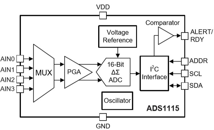
Working or Concept behind ADS1115 IC
As shown in the block diagram below, the IC accepts 4 analog inputs (A0, A1, A2, A3); they are given to the multiplexer whose output is fed to the Programmable Gain Amplifier (PGA). PGA enables the ADS1115 to accept different ranges of inputs as discussed earlier. This range is (+ or -) 256 millivolt to (+ or -) 6.144 volts. The input is then transferred to 16-bit ADC and then to I2C interface block for connecting with the microcontroller through the pins: SDA, SCL, and ADDR. The ADS1115 also has a programmable digital comparator where the analog input is compared with reference voltage and accordingly gives the output as ready (RDY) or alert. These RDY and alert signal can be used to interrupt the microcontroller.
How to use ADS1115 Analog to Digital Converter IC
ADS1115 IC is mounted on an easy-to-use breakout board. You can connect to Arduino, ESP8266, Raspberry Pi, etc. using the two-wire interface (I2C). The ADS1115 is a 16-bit precision ADC with four multiplexed inputs that can be used individually or in pairs for differential measurements. For great precision, it has an inbuilt calibrated reference.
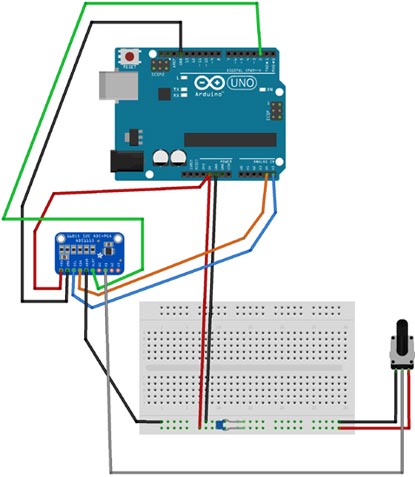
Connections for interfacing ADS1115 Breakout Board with Arduino are given in below table:
|
Arduino board |
ADS1115 |
|
5V |
VDD |
|
GND |
GND |
|
A5 |
SCL |
|
A4 |
SDA |
|
GND |
ADDR |
|
2 |
ALRT |
|
Wiper of 10k pot. |
A1 |
Note: Connect the 10k potentiometer's ends to 5V and GND. Connect a 100nF capacitor to GND and 5V.
Where to use ADS1115 ADC IC
ADCs are used extensively where there’s input from sensors. It is done so because sensors give analog output whereas microcontrollers expect digital input. Hence, ADCs are used to convert the analog to digital input to the microcontroller. Even though most of the microcontrollers today come with built in ACs, sometimes these built-in ADCs don’t suffice the need (they have lesser gain and poor resolution) hence ADS1115 type of compact ADC boards like ADS1115 come in handy.
Applications
- Consumer Electronics
- Portable Instrumentation
- Temperature Measurement Systems
- Battery Voltage and Current Monitoring
- Factory Automation and Process Control
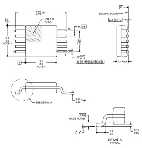
2D Model and Dimensions
If you are designing a PCB or Perf board with this component, then the following picture from the ADS1115 Datasheet will be useful to know its package type and dimensions.