Omron’s new G5PZ-X PCB relay comes in a compact package with 20 A at 200 VDC rated load
An Overview of TTL and CMOS ICs and How to Choose Between Them

It was 1958 when Jack Kilby from Texas Instruments, introduced the world’s first Integrated Circuit (IC) Chip to the electronics industry. This invention spread like wild fire since ICs were more reliable, compact and could also save power compared to the conventional circuits used then. Soon this spread like wild fire and every company started fabricating and adapting Integrated circuits which lead to the modern electronics as we know today. There are many fabrication techniques used in IC manufacturing the two most popular types are the Transistor Transistor Logic (TTL) which got introduced in 1963 and the Complementry Metal Oxide Semiconductor (CMOS) which got introduced in 1968. In this article we will discuss about these two technologies and also how to select between CMOS and TTL IC based on your project design requirement.
What is CMOS?
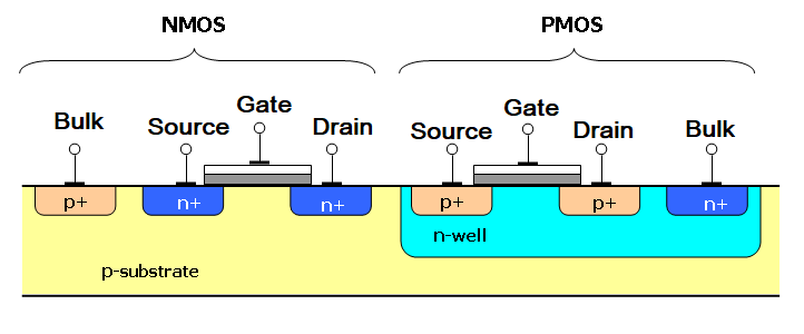
CMOS is the shortened form for Complementary Metal Oxide Semiconductor and it is a technology for fabricating the IC’s which are used in various applications. CMOS is the most common MOSFET fabrication type, it uses the complementary and symmetrical pairs of the p-type and n-type Metal Oxide Field effect transistors for performing the logic functions. The combination of PMOS and NMOS transistor being utilized in a single package is shown below.

Various types of Integrated circuits are constructed using the CMOS technology like the microprocessors, microcontrollers, memory chips and several other digital logic circuits. In static analog circuits like the data converters, image sensors, and transceivers, this technology is used widely. CMOS propagates both logics, high and low or the 0 and 1.
What is TTL?
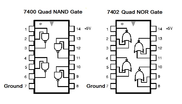
TTL stands for Transistor-transistor Logic. It is a logic family made up of bipolar junction transistors (BJTs). Here, both the functions (logic and amplifying) are performed by the transistors; therefore, it is named as the Transistor-Transistor Logic. An ideal example of TTL logic IC would be Logic Gate ICs like the 7400 NAND or the 7402 NOR Gate.

TTL is the short form of transistor-transistor logic. TTL logic uses multiple transistors having multiple emitters and multiple inputs. The types of the transistor-transistor logic are Standard transistor-transistor logic, Fast transistor-transistor logic, Schottky transistor-transistor logic, High power transistor-transistor logic, Low power transistor-transistor logic, and Advanced Schottky transistor-transistor logic.
TTL logic gates are made up of the Bipolar junction transistors and resistors. There are many variants of TTL developed for various particular purposes like the radiation-hardened TTL packages for space applications and Low power Schottky diodes that can provide an excellent combination of speed and lesser power consumption.
What Is The Difference Between CMOS and TTL? Which one is Better?
The advantage of the CMOS over the TTL chips is that the CMOS has a higher density of logic gates within the same material. TTL chips consume more power as compared to the power consumed by the CMOS chips even at rest. The power consumption of the CMOS depends on various factors and is variable. The clock rate is one of the major factors for power consumption. Higher clock values will result in higher power consumption. When making the comparisons, a single gate in CMOS chip would consume the 10nW of power whereas an equivalent gate on the TTL chip will consume approximately 10mW power. The difference is substantially high and this is why the CMOS chips are always preferred over the TTL chips.
When the design and fabrication are considered, no doubt that the CMOS chips are very delicate and it is difficult to handle as these are highly susceptible to electrostatic discharge. A very minute amount of static electricity could cause damage to the CMOS chips. Thus people often unwillingly damage their chips only by touching the terminals of the CMOS. Some basic differences between CMOS and TTL are explained below:
- CMOS components are generally more expensive when compared to the TTL components. But on system-level, CMOS chips are less expensive as these are smaller in size as compared to the TTL chips.
- There are propagation delays present in both. On average, the propagation delays of TTL are usually 10nS whereas the propagation delays for the CMOS lies between 20 to 50 nS
- CMOS has longer rise and fall times thus digital signals are simpler and less expensive with the CMOS chips.
- There is a substantial difference in the voltage level range for both. For TTL it is 4.75 V to 5.25 V while for CMOS it ranges between 0 to 1/3 VDD at a low level and 2/3VDD to VDD at high levels.
- CMOS technology is more economical and preferred more as compared to the TTL logic.
- The current requirements of the CMOS are low and thus power consumption is limited. Therefore it is easier for the circuits to be designed with the best power management.
- The electromagnetic disruptions CMOS components are more sensitive as compared to the TTL components
- CMOS has one other advantage over the TTL that it has allowed lower noise during the transmission
- The number of standard loads that could be connected to the output of the gate under the normal operation that is the fan-out is 10 for TTL whereas it is 50 for the CMOS.
- The number of standard inputs that can be connected to the gate is the fan in, which is approximately 12-14 for the TTL and for the CMOS it is 10 only.
- CMOS circuits have better noise immunity then the TTL circuits
- The basic gates which are used in the construction of the TTL are the NAND gate whiles both the NAND-NOR gates are used in the CMOS circuits.
Is CMOS a good choice over TTL Component?
Comparing the TTL and CMOS logic families, CMOS has more advantage over the TTL components. It consumes lesser power than the TTL and is more economical as well. The output power of the CMOS is higher and it is smaller in size as well. With higher immunity to the noise, these allow lower levels of noise to transmit while the transmission of the singles. Also, the propagation delays are smaller and thus provide faster transmission of the signals that the TTL circuits. With larger fan outnumber the number of loads can be connected at the output terminal of the CMOS circuit. Though these are delicate and therefore require care and attention while handling them.
Difference between CMOS and TTL - Conclusion
To compare TTL and CMOS, one must think about the points mentioned above. As the CMOS consists of the FET’s and the TTL circuits are made up of BJT, CMOS chips are much faster and efficient. There is a much higher density of the logic functions in a single chip in CMOS as compared to the TTL. Also, the power consumption of the TTL circuits is higher when compared to the power consumption of CMOS. Though the CMOS has lesser power consumption, CMOS chips are more susceptible to the static electric discharge and thus can be damaged easily. CMOS chips could have the TTL logics and could be used for the replacement of the TTL IC.


