MCP4921 12-Bit DAC with SPI Interface
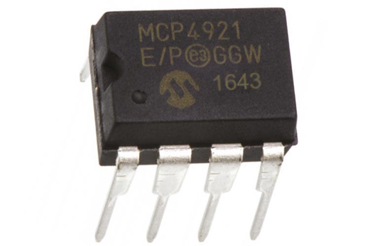
The MCP4921 is a 2.7 – 5.5V, low-power, low DNL, 12-Bit Digital to Analog Converters (DACs) with optional 2X buffered output and SPI interface. The MCP4921 are DACs that provide high accuracy and low noise performance for industrial applications where calibration or compensation of signals (such as temperature, pressure, and humidity) are required.
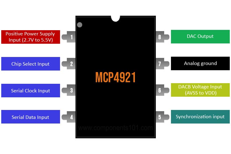
MCP4921 IC Pinout Configuration
|
Pin Number |
Pin Name |
Pin Description |
|
1 |
VDD |
Positive Power Supply Input (2.7V to 5.5V) |
|
2 |
CS |
Chip Select Input |
|
3 |
SCK |
Serial Clock Input |
|
4 |
SDI |
Serial Data Input |
|
5 |
LDAC |
Synchronization input used to transfer DAC settings from serial latches to the output latches. |
|
6 |
VREFA |
DACB Voltage Input (AVSS to VDD) |
|
7 |
AVSS |
Analog ground |
|
8 |
VOUTA |
DAC Output |
Features and Specifications
- 12-Bit Resolution
- ±0.2 LSB DNL (typ)
- ±2 LSB INL (typ)
- Single or Dual Channel
- Rail-to-Rail Output
- SPI™ Interface with 20 MHz Clock Support
- Simultaneous Latching of the Dual DACs w/LDAC
- Fast Settling Time of 4.5 µs
- Selectable Unity or 2x Gain Output
- 450 kHz Multiplier Mode
- External VREF Input
- 2.7V to 5.5V Single-Supply Operation
- Extended Temperature Range: -40°C to +125°C
Note: Complete technical information can be found in the MCP4921 Datasheet, linked at the bottom of this page.
MCP4921 Equivalent DACs
PT8211, DAC7715, DAC0832, MCP4725, AD5421, AD5420, AD5410, AD5422, AD5412
Where to use MCP4921 DAC
The MCP4921 is a single 12-Bit DAC that is useful for many applications. The MCP4921 are DACs that provide high accuracy and low noise performance for industrial applications where calibration or compensation of signals (such as temperature, pressure, and humidity) are required. MCP4921 devices utilize a resistor string architecture, with its inherent advantages of low DNL error, low ratiometric temperature coefficient, and fast settling time. These devices are specified over the extended temperature range. The MCP492X includes double-buffered inputs, allowing simultaneous updates using the LDAC pin. These devices also incorporate a Power-On Reset (POR) circuit to ensure reliable power-up. The MCP4921 is available in the extended temperature range and PDIP, SOIC, MSOP, and TSSOP packages. These devices are useful where we need accurate measurement, like low voltage measurement after a voltage divider stage, SetPoint or Offset Trimming, Sensor Calibration.
The MCP4725 IC has a reference voltage, let’s say 5V (Vref = VDD = 5V), and this reference voltage is divided into 4096 parts (212) and based on the digital value set between 0 and 4095, we can get an accurate analogy voltage equivalent. For example, if the reference voltage is 5V, and we set the digital value as 2048, then we get the output voltage as 2.5V because 2048 is half of 4096. It even has a small step size of 1.22mV (5V/4096 = 1.22mV). We can further decrease this if we’re using 3V as the reference voltage (and this will give us 3V/4096 = 0.73mV).
How to use MCP4921 DAC
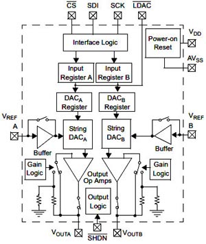
The MCP4921 is a voltage output string DACs. These devices include input amplifiers, rail-to-rail output amplifiers, reference buffers, shutdown and reset management circuitry. Serial communication conforms to the SPI protocol. The MCP492X operates from 2.7V to 5.5V supplies. In the figure below we have shown you a basic example circuit which is a programmable current source.
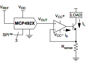
The above figure shows a voltage follower design where a sense resistor is used to convert the DAC’s voltage output into a digitally selectable current source. Adding the resistor network as shown in the above example would be advantageous in this application. The smaller Rsense is, the less power dissipated across it. However, this also reduces the resolution that the current can be controlled with. The voltage divider, or “window”, DAC configuration would allow the range to be reduced, thus increasing resolution around the range of interest. When working with very small sensor voltages, plan on eliminating the amplifier's offset error by storing the DAC's setting under known sensor conditions.
Applications
- Set Point or Offset Trimming
- Sensor Calibration
- Digitally-Controlled Multiplier/Divider
- Portable Instrumentation (Battery-Powered)
- Motor Feedback Loop Control
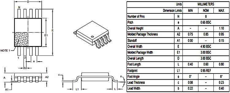
2D Model and Dimensions
If you are designing a PCB or Perf board with this component then the following picture from the Datasheet will be useful to know its package type and dimensions.