AMC7135 350mA Advanced Current Regulator
The AMC7135 is a low dropout current regulator rated for 350mA constant sink current. The low quiescent current and low dropout voltage is achieved by implementing an advanced Bi-CMOS process.
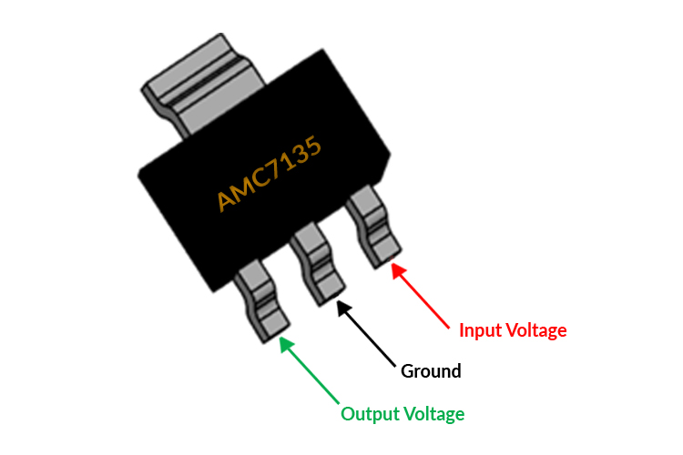
AMC7135 Pinout Configuration
|
Pin Number |
Pin Name |
Pin Description |
|
1 |
Output Voltage (OUT) |
Output Voltage of the Regulator |
|
2 |
Ground |
Ground Pin of the Regulator |
|
3 |
Input Voltage (VDD) |
The input voltage which has to be regulated is given to this pin |
Features & Specifications
- 350mA constant sink current.
- Output short / open circuit protection.
- Low dropout voltage.
- Low quiescent current
- Supply voltage range 2.7V ~ 6V
- 2KV HBM ESD protection
- Operating junction temperature is 125°C
- In-built Current Limiting and thermal protection
- Advanced Bi-CMOS process.
- SOT-89 and TO-252 package
Note: Complete technical details can be found in the AMC7135 Current Regulator datasheet given at the end of this page.
AMC7135 Equivalents
LM1117, LM338, LM317T, XC6206P332MR.
Where to use AMC7135 Current Regulator IC
The AMC7135 Current Regulator IC, meaning it has two Op-Amps inside it and each Op-Amp can be used independently.
The AMC7135 is a low dropout current regulator It is known for its small form factor since it is available as a DCY Package (SMD Component). There are two variants of this IC and you can choose SOT-89 and TO-252 the TO-252 is mildly superior than that of the TO-252.So if you are looking for a SMD component voltage regulator then this IC might be the right choice for you.
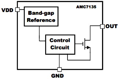
How to use AMC7135 Current Regulator IC
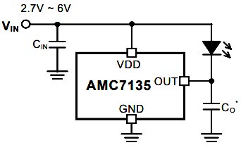
Using the AMC7135 Current Regulator IC is pretty much straight forward, it is a fixed current regulator IC so connecting the power to its input and attaching a load to the output does the job pretty easily. The ground pin needs to be connected to the ground and two decoupling capacitors need to be connected both to the input and the output to make the output current stable. The basic circuit diagram for this IC is shown below.
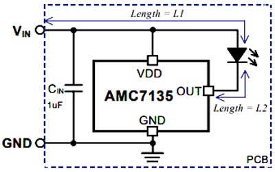
The output capacitor CO may be removed under certain conditions. Please refer to the following figure. If LED and AMC7135 are located in the same PCB, and the length of the routing path L1<10cm & L2<3cm, the output capacitor CO can be neglected.
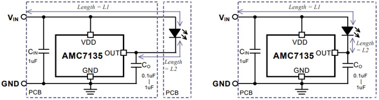
If LED and AMC7135 are located in separate PCBs, or the length of the routing path L1>10cm or L2>3cm, the output capacitor CO should be added. Typically, capacitance of 0.1uF ~ 1uF is recommended and 1uF is needed when L2 is much longer than 3cm.
For more information you can check out the datasheet of the device linked in the bottom of the page.
Applications
- Power LED driver
- Cap Lamp
- Refrigerator Lighting
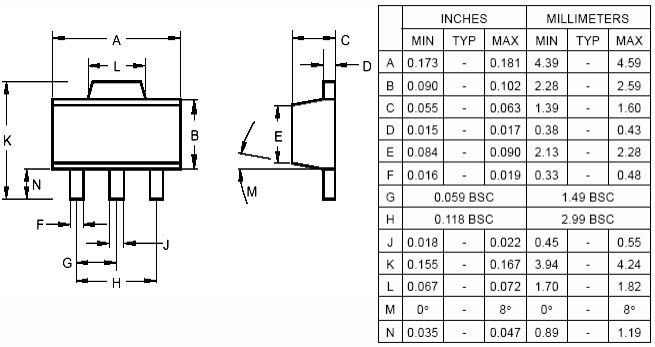
2D Model and Dimensions
If you are designing a PCB or Perf board with this component then the following picture from the Datasheet will be useful to know its package type and dimensions.