12-0-12 Center Tapped Transformer
Transformer Terminal Description
|
No: |
Terminal Name |
Description |
|
1 |
I1 and I2 |
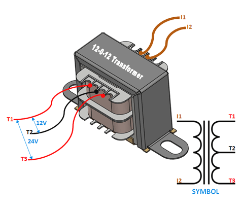
These are the input wires for the transformer, it is connected to the phase and neutral of AC mains |
|
2 |
T1 and T3 |
There are the output terminals of the Transformer, the voltage across it will be 24V AC |
|
3 |
T2 |
This is the centre tapped wire of the transformer; this wire can be combined with either T1 or T3 to get 12V AC across it. It’s very useful for rectifier circuits |
12-0-12 Centre Tapped Transformer Specifications
- Step-down Centre tapped Transformer
- Input Voltage: 220V AC at 50Hz
- Output Voltage: 24V, 12V or 0V
- Output Current: 1A
- Vertical mount type
- Low cost and small package
You can find more details at the Centre Tapped Transformer datasheet provided at the end of this article.
Other Center Tapped Transformers
12-0-12 (2A,3A,5A), 6-0-6 (1A,2A,3A,5A), 24-0-24 (1A,2A,3A,5A), 18-0-18 (1A,2A,3A,5A)
Other Transformers
Step-up Transformers, Secondary Transformers, Pulsating transformers, Auto Transformer
Where to Use Centre Tapped transformer
A centre-tapped transformer also known as two phase three wire transformer is normally used for rectifier circuits. When a digital project has to work with AC mains a Transformer is used to step-down the voltage (in our case, to 24V or 12V) and then convert it to DC by using a rectifier circuit. In a center-tapped transformer the peak inverse voltage is twice as in bridge rectifier hence this transformer is commonly used in full wave rectifier circuits.
How to use Center Tapped Transformer
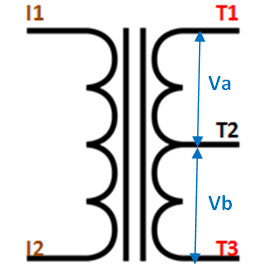
The operation and theory behind a Center tapped transformer is very similar to a normal secondary transformer. A primary voltage will be induced in the primary coil (I1 and I3) and due to magnetic induction the voltage will be transferred to the secondary coil. Here in the secondary coil of a centre tapped transformer, there will be an additional wire (T2) which will be placed exactly at the center of the secondary coil, hence the voltage here will always be zero.
If we combine this zero potential wire (T2) with either T1 or T2, we will get a voltage of 12V AC. If this wire is ignored and voltage across T1 and T2 is considered then we will get a voltage of 24V AC. This feature is very useful for the function of a full wave rectifier.
Let us consider the voltage given by the first half of the secondary coil as Va and the voltage across the second half of the secondary coil as Vb as shown in the diagram below

As we know the voltage across the coil depends on the number of turns on the primary and secondary coil. Using the turns ratio formulae we can calculate the secondary voltage as:
Va = (Na / Np) * Vp
Vb = (Nb / Np) * Vp

Where,
Va = Voltage across the first half of Secondary coil
Vb = Voltage across the second half of Secondary coil
Vp = Voltage across the Primary coil
Na = Number of turn in the first half of Secondary coil
Nb = Number of turn in the second half of Secondary coil
Np = Number of turn in the Primary coil
Applications
- Rectifier circuits
- AC-AC step down
- Full wave rectifiers


