JRC4558 Dual Operational Amplifier
The JRC4558 is a high performance monolithic dual operational amplifier. JRC4558 internally compensated and constructed on a single silicon chip. The high voltage gain (100 dB typ.), good input impedance (5 MΩ typ.) and versatile power supply (± 4 to 18 Volts) make it perfect to fit in pedal circuit designs.
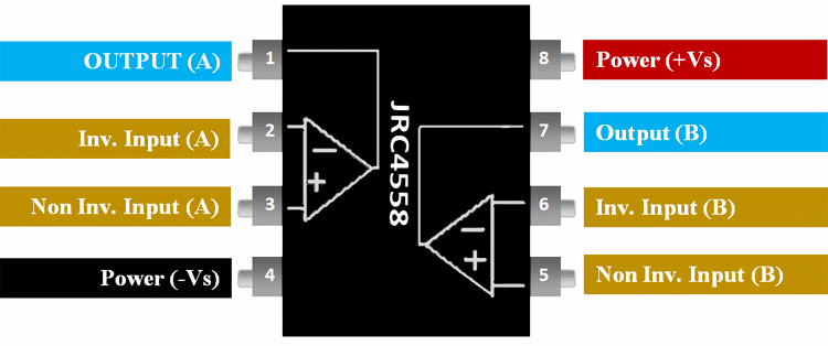
Pin Description of JRC4558:
|
Pin Number |
Pin Name |
Description |
|
1 |
OUT (A) |
The output pin of the Op-amp A |
|
2 |
Inverting Input (A) |
The Inverting input pin of the Op-Amp A |
|
3 |
Non- Inverting Input (A) |
The Non - Inverting Input Pin of Amplifier A |
|
4 |
Power (-Vs) |
Negative supply terminal |
|
5 |
Reference |
The Non - Inverting Input Pin of Amplifier B |
|
6 |
Output |
The Inverting input pin of the Op-Amp B |
|
7 |
Power (+Vs) |
The output pin of the Op-amp B |
|
8 |
+VS |
Positive supply terminal |
Features and Specifications of JRC4558
- Supply Voltage Range: ± 5V to ± 15V
- Bandwidth: 3MHz
- No. of Amplifiers: 2
- No. of Pins: 8
- Operating Temperature Max: 70°C
- Operating Temperature Min: 0°C
- Slew Rate: 1.7V/µs
- Available in 8-Pin DIP and SOP Package
Note: Complete Technical Details can be found at the JRC4558 datasheet give at the end of this page.
Alternative Op-Amps: LM158, LM158A, LM358, LM358A, LM2904, LM2904Q, LM4558, LM747
Where to Use JRC4558
JRC4558IC can be used in general purpose op-amp operation circuits like comparator, differential amplification or mathematical operations. Moreover, the device specifically designed for applications like transducer amplifiers, dc amplification blocks to be implemented more easily in single-supply-voltage systems. For example, these devices can be operated directly from the standard 5V supply used in digital electronics without additional -5V supply. In addition with two of those op-amps on board, the device can perform two different functions at a time that comes in handy in applications. The device is popular among hobbyists and engineers for being low cost and good performance.
How to Use JRC4558
As mentioned above JRC4558 is a dual op-amp IC. The internal connection diagram of JRC4558 is shown below.
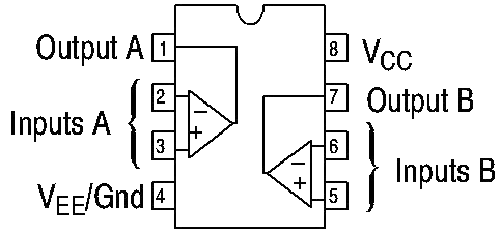
Now let us take a single op-amp from the available two and construct a simple JRC4588 circuit diagram to explain its aplications.
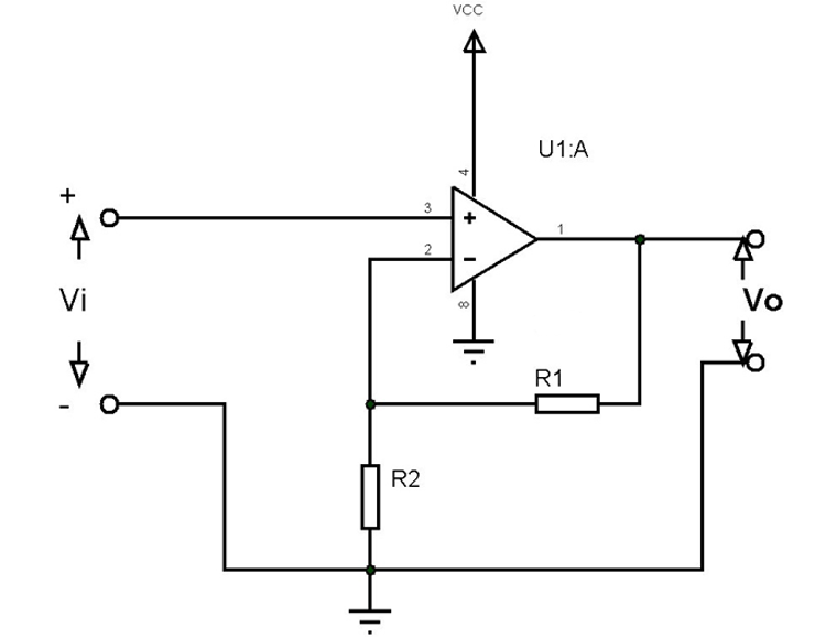
In the above circuit, the op-amp acts as a Non-Inverting Amplifier (Since the input is given to the Non-inverting terminal of the op-amp) and output is provided as Vo. Also, the device is powered from a single voltage source of VCC. We have the equation for the output Vo =Input voltage * Gain .
Vout = Vi * (1+R1/R2)
For example: Say R1 = 100, R2 = 10 and Input voltage Vi = 20mV. Then we will have Vo = 20m*(1+10)=220mV
With that, we have realized the amplifier circuit of the op-amp and in a similar way, we use the device to design all other application circuits of an op-amp.
Applications of JRC4558
- Ground Referenced Single Amplifiers in Automobile and
- Portable Instrumentation
- Sample and Hold Amplifiers
- Long Duration Timers/Multivibrators (Microseconds Minutes-Hours)
- Photocurrent Instrumentation
- Intrusion Alarm System
- Comparators
- Function Generators
- Instrumentation Amplifiers
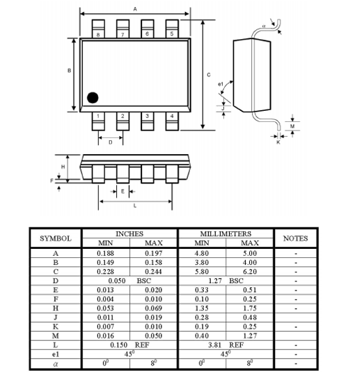
2-D Model of JRC4558
2-D dimensions for JRC4558 8-pin SOP package is given below