

Omron’s new G5PZ-X PCB relay comes in a compact package with 20 A at 200 VDC rated load
Performance Comparison Between Shunt, Hall, and IC based Current Sensing Designs

From compact shunt resistors to bulky current transformers, engineers adopt a wide range of current measurement techniques in their designs to measure and monitor current in their circuits. But why is it so important? Because, in electronics, the circuit works with two major sources, voltage (which is the potential difference) and current (Which is the flow of charge between a path where potential difference exists). Now, to get a reading of sensor data or to know how a circuit is behaving (Normal operation or short circuit condition), a crucial step is involved where current measurement is required.
Now, in a system, how much precision current sensing is required completely depends on the application requirement. In some cases 1% reading error can be crucial on the other hand, in some places reading tolerances does not matter much. However, in this article, we will describe the Top Three Current sensing techniques and differentiate the application characteristic, complexity, implementation cost, and error margins. So without further ado let's get right into it.
Current Shunt using Current Sense Resistor
When it comes to current sensing, almost all engineers will agree that they will think to apply current sense shunt resistors into the system if the application permits them to do so. A current sensing resistor is a low-value resistor in series that is used to sense the current This is because of the simplicity and without any massive component counts, few resistors and op-amp could be much more beneficial to make this possible. It is the most common way to measure current where the current is sensed by sensing the voltage drop across a shunt resistor.
The success of accurate sensing lies between two things, the parametric values of both the sense resistor and current-sense amplifier which leads to a perfect component selection and the proper PCB layout of the connections where the trace resistance, capacitance of the op-amp traces are critical to avoid an accuracy reduction.
Now, the sense resistor needs to be selected first where the value, wattage, ppm, and tolerances are critical. One of the most important design decisions to make when using a current-sense amplifier is the selection of the current-sense or shunt resistor where the resistance value and wattage value are the major criteria. Once you’ve selected the resistor, you’ll need to pay attention to its printed circuit board (PCB) layout to achieve accurate measurement results. If you want to learn more about PCB Design, do check out our previous articles on the topic.
The value of the resistor depends on getting a desired maximum voltage drop at the highest current supported by the application. It may also depend on the power-loss budget, as larger values tend to produce larger power loss converted to proportional heat dissipation. Once the value is confirmed, it is time to determine the required wattage of the current-sense resistor. It should be higher than the calculated typical value. Now, the next parameter to consider the resistor tolerance as the current sense accuracy could be excellent if 0.01% or less than that, as it will directly impact the accuracy of the sensed voltage which will further be converted to the current flowing through the resistor. However, it is obvious to quote another important parameter of the resistor that is often overlooked by the designer–the resistor temperature coefficient or ppm. In a resistor, the temperature coefficient is specified as parts per million per degree Celsius, and it’s a very important parameter since the temperature of the resistor will rise significantly due to the power dissipation. In a real application, the tolerance is directly connected with this ppm value as the temperature drift increases in significant amounts.
The image given below is an example of single resistor current sensing where the voltage drop is significant, as per Ohm’s Law.
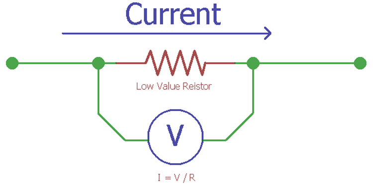
However, even after this consideration of the resistor, another important aspect is the differential amplifier. A well-designed current sense amplifier could differentiate a small number of voltage differences in the high side or low side current sensing. The measurement requires proper differential routing on the PCB as well to compensate for the resistance differences between the positive and negative input. Kelvin sensing technology is helpful in this regard.
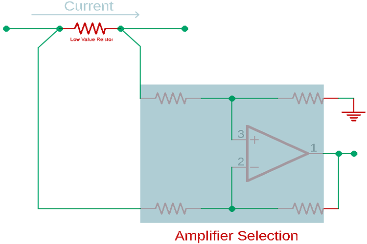
Few examples of current sensing amplifier – INA210, INA250, etc.
Overall impression of this sensing-
- It is a significantly low cost where the cost implies current sensing resistor value and tolerances. It is also dependent on the op-amp. It can be a simple op-amp or can be a dedicated differential op-amp designed for current sensing applications.
- Design aspects are rather simple.
- The error margin is less if designed with properly selected parts.
- Directly it is not suitable to sense AC current which requires isolation.
- Not suitable for very high current applications (20A or more) since there are better choices in such range.
- Careful construction is required for high side and low side current sensing. It may require a different configuration on the op-amp section.
Integrated Hall Element Current Sensing
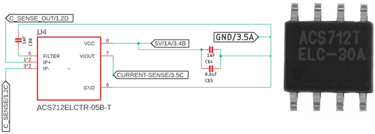
One of the most used current sensing elements for current sensing is the Hall element current sensing where an integrated IC using a Hall Effect sensor directly measures current in an isolated condition when current passes through the terminal. It is best suited for high current measurement above 5A and ranges up to 30 - 50A. It uses the principle of converting the magnetic field produced around the current being measured to voltage using the Hall Effect.
This type of integrated Hall Effect sensor is available in small IC packages. It does not require an additional circuit to run through since they already have a built-in op-amp in a single package where maybe a simple voltage reference is required in some cases. It has space-saving features due to the small IC footprint and no additional components.
Few examples can be easily available:
- ACS712 (Has different variants for +/-5A, +/-10A, +/-20A).
- TMCS1100 from Texas Instruments (Upto +/-25A)
This type of IC galvanically isolates the current line, thus it does not have any electrical interference between the sensed path and the sensing circuitry. It has low error arguing typically ranges from +/-0.5% to +/-1% tolerances. The current can be unidirectional or bi-directional as well, where the output voltage doesn't change suitable for analog and digital circuits.
Overall impression of this sensing technique:
- It is a significantly low cost but can be higher than the shunt resistor sensing method.
- Design aspects are simple
- Directly suitable to sense AC Current and DC
- Provides isolation between sensed element and sensing circuit
- Suitable for high current applications (20A or more)
Conventional Hall Effect Current Sensing
This is the same current sensing technique as the Integrated Hall-Effect current sensing technique. It also uses a magnetic field generated by the current flow, which is converted to a voltage by a Hall Effect element placed inside the ferromagnetic core. It is not available in any IC packages; rather it uses the sensor that could be placed on the power line wire or the BUS Bar.
It could provide a very high amount of current sensing range, for example, 200A - 400A, etc. However, the precision of this sensor is typically low and does involve several components, as the output voltage is small enough to be used as a measurement reference point. It requires a differential amplifier with gain control and a temperature compensation circuit. To run those devices, one also needs a regulator.
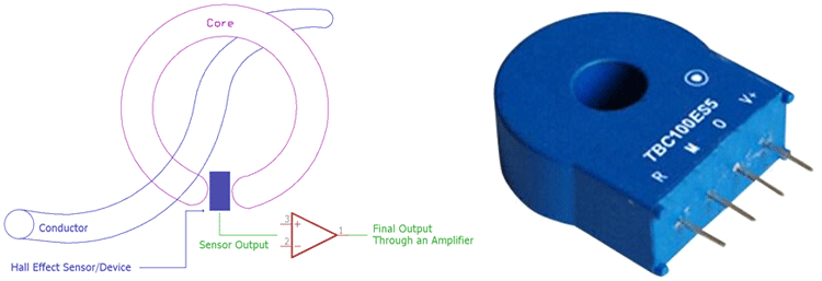
It features high component cost, often available in small conductor through-hole packages that can be easily soldered on a PCB or as a CT transformer or Clamp transformer that can be used out of the PCB board.
Overall impression of this sensing technique:
- The hall element is low-cost, but the additional circuits can be higher in price compared to other methods.
- Design aspects are a little bit complex.
- Directly suitable to sense AC Current and DC.
- Provides isolation between sensed element and sensing circuit.
- Suitable for high current applications (100A or more).
Thus, it is a brief of information about current sensing techniques depending on the different aspects. However, the selection of technique is always dependable on the application requirement and the targeted price of the application.
If you have any questions about what to use or how to use or the selection of the components, leave a comment. We will help you in making current sensing as simple as possible.


