

Omron’s new G5PZ-X PCB relay comes in a compact package with 20 A at 200 VDC rated load
How does AC Coupling and DC Coupling help in Reducing Noise for Signal Measurement?

Detection and measurement of electronic signals is a task that involves some precision. Often the input stage contains an Op-Amp integrator to measure small changes in input. If the input has any amount of DC, the output will saturate quickly, because an integrator works best with an AC signal to accumulate the small changes in the input stage. This kind of problem calls the design engineers to use the right kind of coupling circuits for the measurement.
What is AC Coupling?
AC coupling involves getting rid of the DC offset of a signal. This is often accomplished by adding a capacitor in series with the circuit from which you want to remove AC signals.
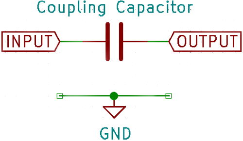
Without getting too much into the math, a capacitor has the ability to block DC and only let AC signals through. Since a capacitor basically just consists of an insulator sandwiched by two conductors, there is no path for electrons to flow and current is blocked. However, a small charge on one terminal can induce an electric field and attract the opposite charge on the other terminal which causes charges to be ‘pushed’ around on the other side because of the electric field. This movement of charges happens only when charges are added or removed from one side, in other words current ‘flows’ through a capacitor only when there is a changing voltage across the capacitor.
Since a capacitor acts like a frequency dependent resistor, a coupling capacitor automatically attenuates low frequency signals, this is something to take note of.
What is DC Coupling?
DC coupling is essentially connecting the input directly to the signal being measured. So, effectively DC coupling does nothing, it allows both AC and DC signals to be measured. Since the input is being connected directly, there is a small risk of shorting, improper impedance matching or signal reflection, which is why inputs are usually terminated with a resistor. Oscilloscopes are usually terminated with 1M, RF circuits with 50 Ohm, and video signals with 75 Ohms.
AC Coupling vs DC Coupling
It is not fair to compare AC coupling with DC coupling, because both are different all together and have its own unique application. But in general, DC coupling when we need to measure both AC and DC component of a signal and AC coupling is used when we need to measure only the AC component of the signal.
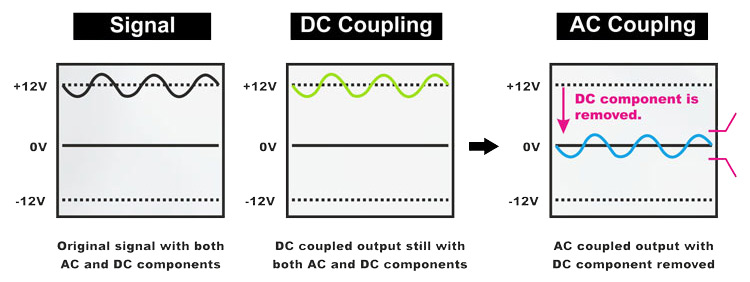
In other words, the output from DC coupling will be similar to the original signal, and the output from AC coupling will have the DC component removed from the original signal as illustrated in the image above.
Where should you use AC coupling and DC coupling?
The most important use of coupling is in measurement. All oscilloscopes come with oscilloscope coupling options either to AC couple or DC couple. AC coupling is used when the DC offset of a signal does not matter. It also removes DC noise from other high-frequency signals. DC coupling let all signals pass through and be measured.
Speakers of all types are almost always AC coupled through a big capacitor. This is because a DC current in a speaker coil puts it in a fixed position depending on the current, so when the sound signal passes through it the dynamic range on one side will decrease. The DC current through the speaker also decreases efficiency due to increased I2R losses.
AC coupling is also used to measure power supply noise. The absolute DC value of the output voltage does not matter in this case, only the noise riding on that signal needs to be measured. By AC coupling the output voltage, only the noise is seen and can be measured.


