TL072 OP-AMP IC
Pin Configuration
|
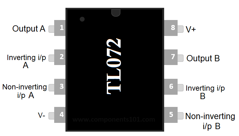
PIN No. |
Name |
Description |
|
1 |
1OUT |
Output of first op-amp |
|
2 |
1IN- |
Inverting input for first op-amp |
|
3 |
1IN+ |
Non-inverting input for first op-amp |
|
4 |
Vcc- |
Ground |
|
5 |
2IN+ |
Non-inverting input for first op-amp |
|
6 |
2IN- |
Inverting input for first op-amp |
|
7 |
2OUT |
Output of second op-amp |
|
8 |
Vcc+ |
Supply voltage |
TL072 Features
- It has low power consumption, Input-bias currents and Offset currents
- Provided with the short circuit protection
- Operation of IC is Latch-up free
- Having two op-amp inside or called as dual op-amp IC.
- Input impedance is high
- Internal Frequency Compensation
- Wide common-mode (up to VCC+) and differential voltage range
Technical Specifications
- Distortion of Harmonic is low (normally 0.003%)
- Low noise at the operation
Vn = 18 nV/√Hz (Typical) at f = 1 kHz - Having high slew rate (normally 13 V/μs)
- Supply voltage ranges from 6 to 36v
- Having infinite output short circuit duration
- Storage temperature ranges -65 to 150 °C
- Operating Temperature is -40 to 125 °C
- Output current is 10mA (normally)
TL072 Equivalent ICs
LM358, NE5532, OPA827, LT1972, ADA4610-2
Brief Description
These are high-voltage JFET-input operational amplifiers with low noise versions and high slew rate. The Input bias and Offset currents is also low. It’s a dual Op-amp IC means it contain two op-amp inside. This TL07x series come with low harmonic distortion and low noise which makes it fit for the use where high-accuracy needed. It also used in the application of audio pre-amplification.
Where to use IC TL072?
TL072 is mainly used where high-accuracy is needed with respect to low harmonic and noise, as used for audio pre-amplification. The audio pre-amplification means for getting output audio with low noise, interference, distortion and also used for controlling the volume, bass and treble. It also compares the voltage like the other op-amp ICs do. So, can be used as a voltage comparator IC.
How to use IC TL072?
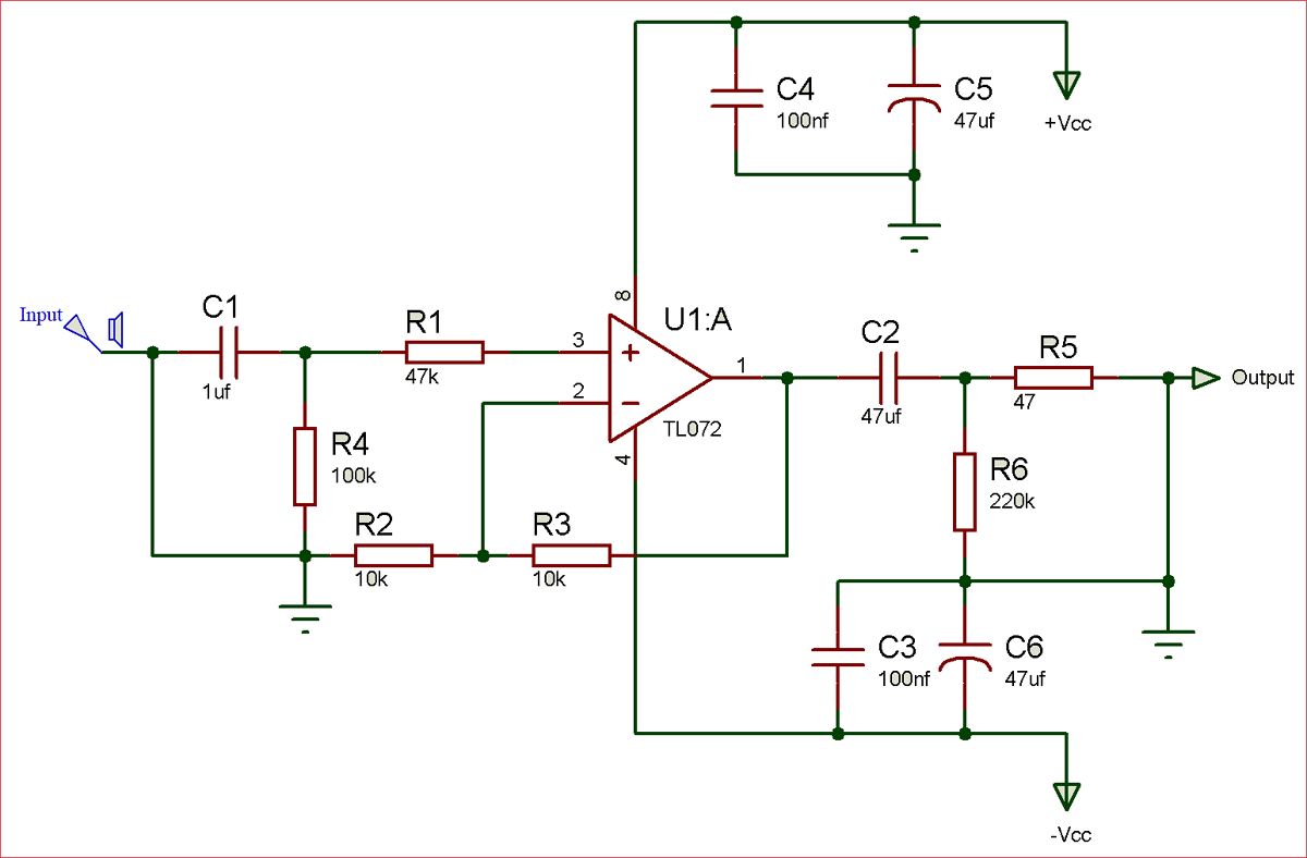
We can use this IC for audio pre-amplification or for better sound quality with having a low price of it with a high accuracy. In the circuit, as the audio input is attached it will receive from the output with low noise and distortion. We can increase the value of resistor R4 due to having high input impedance. R1 is used for impedance balancing, which helps in getting low distortion. R2 and R3 are negative feedback resistors, used for measuring the output signal. If the value of R2 and R3 is placed too high then the noise will increase and if it is too low then the noise will be lower, but it may increase distortion as the load on IC gets high. R6 is used to discharge or empty the C2 flows in order to reduce noise strikes.

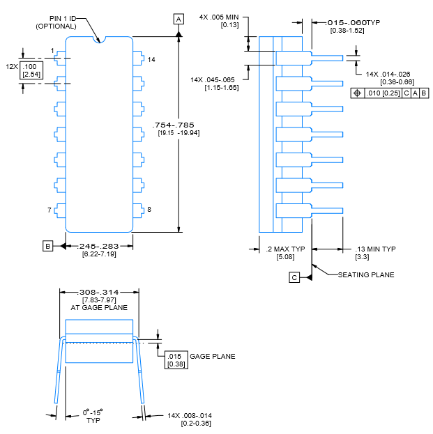
2D-Model and Dimensions


