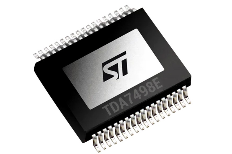
TDA7498E Class-D Audio Amplifier
TDA7498E is a class-D audio amplifier commonly used for stereo applications and mono BTL applications. It is available in dual BTL with a power output of 160W + 160W. It can be used as mono BTL with a power output of 220W. It has 36 pins package with exposed pin-up (EPU) with a separate heatsink.
TDA7498E is a high-frequency amplifier. It has four selectable fixed gain settings. It has an overcurrent protection circuit to protect the device from unwanted current peaks. The device will automatically shut down when the current exceeded a threshold value. When the fault is removed, the device will recover automatically.
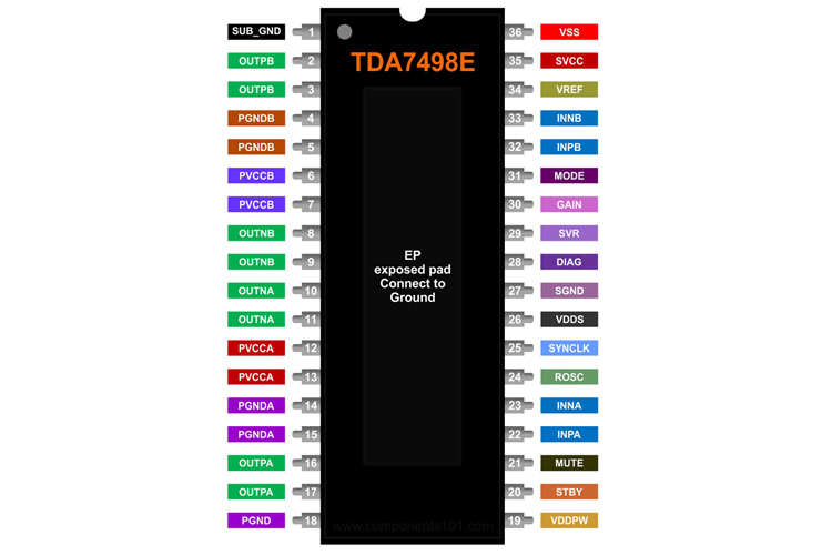
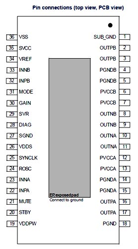
TDA7498E Pinout Configuration
|
Pin No. |
Pin Name |
Pin Description |
Channel |
|
1 |
SUB_GND |
Connect to the frame |
|
|
2,3 |
OUTPB |
Positive PWM |
right channel |
|
4,5 |
PGNDB |
Power stage ground |
|
|
6,7 |
PVCCB |
Power supply |
|
|
8,9 |
OUTNB |
Negative PWM output |
|
|
10,11 |
OUTNA |
Negative PWM output |
left channel |
|
12,13 |
PVCCA |
Power supply |
|
|
14,15 |
PGNDA |
Power stage ground |
|
|
16,17 |
OUTPA |
Positive PWM output |
|
|
18 |
PGND |
Power stage ground |
|
|
19 |
VDDPW |
3.3-V (nominal) regulator output referred to the ground for power stage |
|
|
20 |
STBY |
Standby mode control |
|
|
21 |
MUTE |
Mute mode control |
|
|
22 |
INPA |
Positive differential input |
left channel |
|
23 |
INNA |
Negative differential input |
|
|
24 |
ROSC |
Master oscillator frequency-setting pin |
|
|
25 |
SYNCLK |
Clock in/out for external oscillator |
|
|
26 |
VDDS |
3.3-V (nominal) regulator output referred to ground for signal blocks |
|
|
27 |
SGND |
Signal ground |
|
|
28 |
DIAG |
Open-drain diagnostic output |
|
|
29 |
SVR |
Supply voltage rejection |
|
|
30 |
GAIN |
Gain setting input |
|
|
31 |
MODE |
Enables stereo or mono BTL mode of operation |
|
|
32 |
INPB |
Positive differential input |
right channel |
|
33 |
INNB |
Negative differential input |
|
|
34 |
VREF |
Half VDDS (nominal) referred to ground |
|
|
35 |
SVCC |
Signal power supply |
|
|
36 |
VSS |
3.3-V (nominal) regulator output referred to a power supply |
|
Features & Specifications
- 160W + 160W output power at THD = 10%, RL = 4 Ω, VCC = 36 V
- 1X220W output power mono parallel BTL at THD = 10%, RL = 3 Ω, VCC = 36 V
- Wide-range single-supply operation (14 - 36 V)
- Maximum DC supply voltage VCC: 45 V
- Maximum voltage for input pins: -0.3 to 4 V
- Total quiescent current Iq: 60 mA
- Output Power Po: 160 W @ THD = 10%, 120 W @ THD = 1%
- Efficiency η = 85%
- Rise time and fall time: 35 ns
- Supply voltage rejection ratio (SVRR): 55 dB
- High efficiency (η = 85%)
- Small offset less than 20 mV
- Differential inputs minimize common-mode noise
- Parallel BTL function using the MODE pin
- Four selectable, fixed gain settings of nominally 23.8 dB, 29.8 dB, 33.3 dB, and 35.8 dB
- Standby and mute features
- Smart protection and Thermal overload protection
Function Modes of TDA7498E Audio Amplifier
This device works in three modes: Standby, Mute, and Play.
- Standby: STBY < 0.5 V, MUTE = X
- Mute: STBY > 2.5 V, MUTE < L
- Play: STBY > 2.5 V, MUTE > H
TDA7498E Audio Amplifier Equivalents
STEVAL-CCA044V1, TDA8953, TPA3116
Note: Complete technical details about this IC can be found in the TDA7498E datasheet, given at the end of the page.
How to Use TDA7498E Audio Amplifier
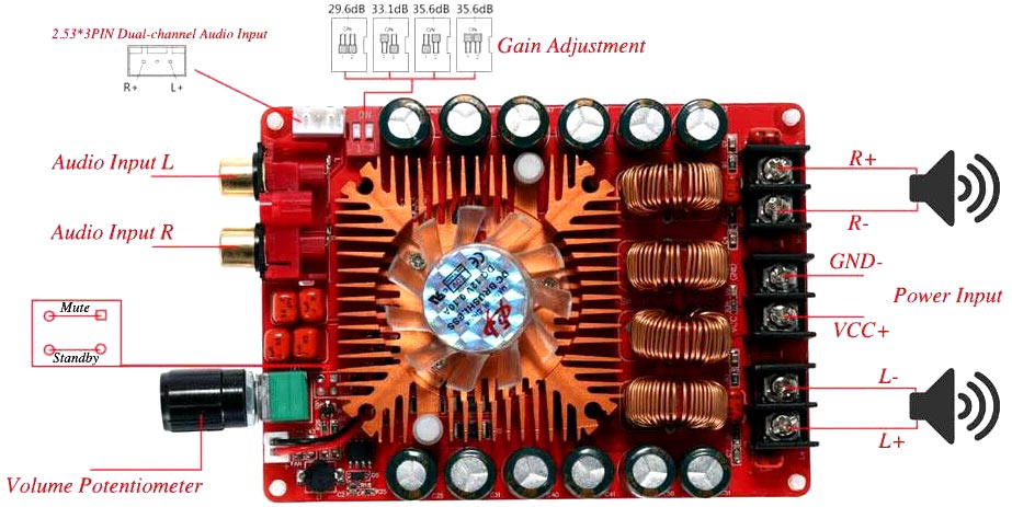
TDA7498E is a dual-channel amplifier. Hence, we can connect two speakers with this amplifier. The power of each channel is 160 W. If you want to connect only one speaker, you can connect with any channel. Here, two channels are named as the left channel and right channel.
You can connect the speaker directly with the audio jack given on the left side. Two audio input pins are available for each channel. There is a 3-pin dual-channel audio input beside the audio jack. You can connect the speaker with this pin also. There is another way to connect the speaker by direct +/- wire connection. On the right side of the board, we have three 2 pins. One pin is for the left channel, the second pin is for VCC/ground, and the third pin is for the right channel. There is a +/- notation behind these pins to connect the +/- wire of speakers.
You can find a potentiometer on the left side of the board. This potentiometer is used to control the voice of sound. There is a gain selector switch. By which we can set the output gain. Higher the gain loud the sound. Hence, for a high volume set both switches are at a high position.
Applications
- Speaker output in LCD Monitors / TV Projectors
- Speaker output amplifier in Notebook Computers
- Can be used for Portable Speakers, Portable DVD Players, Game Machines
- Any possible amplifier-based project where small space and 5V output is available.
2D Model and Dimensions
If you are designing a PCB or Perf board with this component then the following picture from the Datasheet will be useful to know its package type and dimensions.
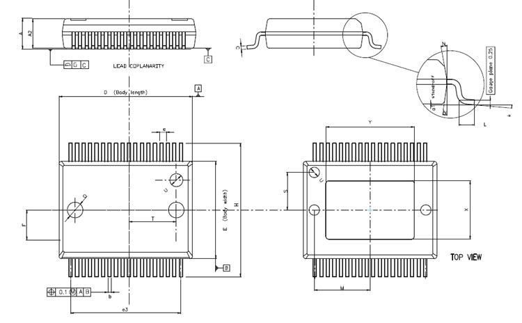
|
Symbol |
mm |
||
|
|
Min. |
Typ. |
Max. |
|
A |
2.15 |
- |
2.45 |
|
A2 |
2.15 |
- |
2.35 |
|
a1 |
0 |
- |
0.1 |
|
b |
0.18 |
- |
0.36 |
|
c |
0.23 |
- |
0.32 |
|
D |
10.1 |
- |
10.5 |
|
E |
7.4 |
- |
7.6 |
|
e |
- |
0.5 |
- |
|
e3 |
- |
8.5 |
- |
|
F |
- |
2.3 |
- |
|
G |
- |
- |
0.1 |
|
H |
10.1 |
- |
10.5 |
|
h |
- |
- |
0.4 |
|
k |
0 |
- |
8 degrees |
|
L |
0.55 |
- |
0.85 |
|
M |
- |
4.3 |
- |
|
N |
- |
- |
10 degrees |
|
O |
- |
1.2 |
- |
|
Q |
- |
0.8 |
- |
|
S |
- |
2.9 |
- |
|
T |
- |
3.65 |
- |
|
U |
- |
1 |
- |
|
X |
4.1 |
- |
4.7 |
|
Y |
6.5 |
- |
7.1 |

