MPR121 Capacitive Touch Sensor Module
In certain projects, it might not be practical to include push-buttons for inputs. The constraints might be spatial or related to parts cost. In these cases, a capacitive touch sensor IC can turn an exposed PCB surface into a push-button that is activated upon touch. The MR121 module performs this function with 12 input channels.
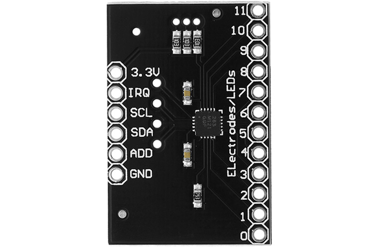
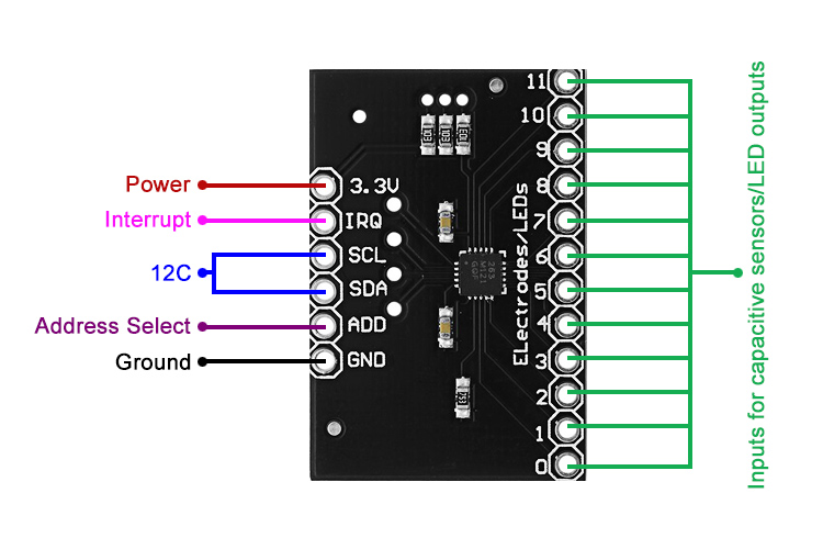
MPR121 Module Pinout Description
|
Pin Name |
Description |
|
3.3V |
Power supply input pin, nominally 3.3V |
|
IRQ |
Open-drain interrupt output |
|
SCL |
I2C Serial Clock |
|
SDA |
I2C Serial Data |
|
ADD |
I2C Address Selector |
|
GND |
IC Ground Reference |
|
0 - 11 |
Inputs for capacitive sensors/LED outputs |
Features
- 1.7V to 3.6V supply voltage and 29uA supply current
- 12 capacitive sensing inputs
- 8 LED/GPIO pins
- I2C interface with interrupt
Alternate Capacitive Touch Sensor Module
TTP223, TTP226
Related Components:
MPR121 IC, resistors, capacitors, inductors
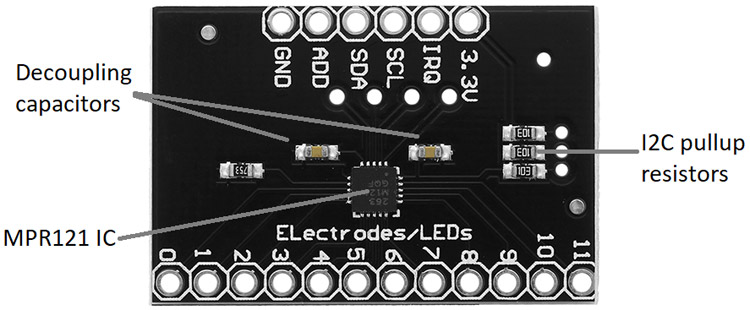
Brief About Capacitive Touch Sensor Module
The MPR121 module consists of the MPR121 IC itself, and some supporting resistors and capacitors.
How To Use Capacitive Touch Sensor Module
A capacitor is an electronic component that stores charge temporarily. Particularly useful is its property of making the voltage increase linearly when a constant current is applied to it, or exponentially when connected through a resistor to a constant voltage. This property is used very commonly in timing applications. If one end of this capacitor is connected to this circuit and the other end is left floating or is formed by a floating body, the time constant of the circuit changes. This is the operating principle behind a capacitive touch sensor – one end is connected to an IC that uses the time constant to generate a signal, and the other end is formed by the finger touching the “contact”. The circuit is completed through parasitic capacitances to the ground.
The MPR121 is an IC that has all the necessary circuits to implement twelve such capacitive touch sensors. The twelve pins can be connected to electrodes, which are simply metallic pads. Eight of these pins also double as LED driver outputs or GPIOs.
The I2C protocol is used to communicate with the IC. Four different addresses can be selected by connecting the ADD pin to GND, VCC, SCL, or SDA.
Applications
- Computer peripherals
- MP3 players
- Remote controls
- Lighting controls