MG82F6D17 8051 Based Low-Power Low-Cost Microcontroller
The MG82F6D17 is a single-chip microcontroller based on a high-performance 1-T architecture 80C51 CPU that executes instructions in 1~7 clock cycles (about 6~7 times the rate of a standard 8051 device) and has an 8051 compatible instruction set. Therefore, at the same performance as the standard 8051, the MG82F6D17 can operate at a much lower speed and thereby greatly reduce the power consumption. The main benefit of this microcontroller is the cost.
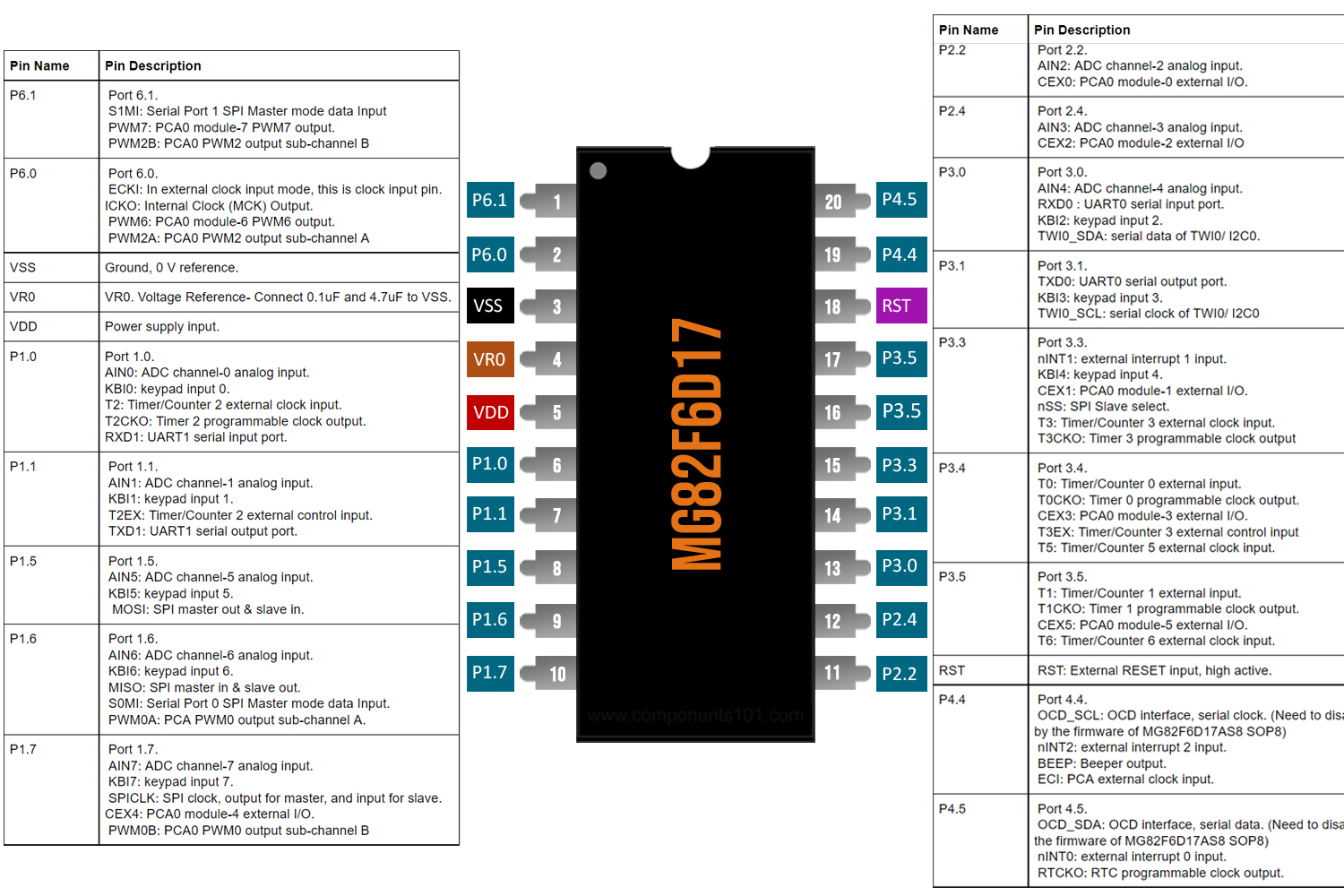
MG82F6D17 Pinout Configuration
|
Pin No. |
Pin Name |
Pin Description |
|
1 |
P6.1 |
Port 6.1. S1MI: Serial Port 1 SPI Master mode data Input PWM7: PCA0 module-7 PWM7 output. PWM2B: PCA0 PWM2 output sub-channel B |
|
2 |
P6.0 |
Port 6.0. ECKI: In external clock input mode, this is clock input pin. ICKO: Internal Clock (MCK) Output. PWM6: PCA0 module-6 PWM6 output. PWM2A: PCA0 PWM2 output sub-channel A |
|
3 |
VSS |
Ground, 0 V reference. |
|
4 |
VR0 |
VR0. Voltage Reference- Connect 0.1uF and 4.7uF to VSS. |
|
5 |
VDD |
Power supply input. |
|
6 |
P1.0 |
Port 1.0. AIN0: ADC channel-0 analog input. KBI0: keypad input 0. T2: Timer/Counter 2 external clock input. T2CKO: Timer 2 programmable clock output. RXD1: UART1 serial input port. |
|
7 |
P1.1 |
Port 1.1. AIN1: ADC channel-1 analog input. KBI1: keypad input 1. T2EX: Timer/Counter 2 external control input. TXD1: UART1 serial output port. |
|
8 |
P1.5 |
Port 1.5. AIN5: ADC channel-5 analog input. KBI5: keypad input 5. MOSI: SPI master out & slave in. |
|
9 |
P1.6 |
Port 1.6. AIN6: ADC channel-6 analog input. KBI6: keypad input 6. MISO: SPI master in & slave out. S0MI: Serial Port 0 SPI Master mode data Input. PWM0A: PCA PWM0 output sub-channel A. |
|
10 |
P1.7 |
Port 1.7. AIN7: ADC channel-7 analog input. KBI7: keypad input 7. SPICLK: SPI clock, output for master, and input for slave. CEX4: PCA0 module-4 external I/O. PWM0B: PCA0 PWM0 output sub-channel B |
|
11 |
P2.2 |
Port 2.2. AIN2: ADC channel-2 analog input. CEX0: PCA0 module-0 external I/O. |
|
12 |
P2.4 |
Port 2.4. AIN3: ADC channel-3 analog input. CEX2: PCA0 module-2 external I/O |
|
13 |
P3.0 |
Port 3.0. AIN4: ADC channel-4 analog input. RXD0 : UART0 serial input port. KBI2: keypad input 2. TWI0_SDA: serial data of TWI0/ I2C0. |
|
14 |
P3.1 |
Port 3.1. TXD0: UART0 serial output port. KBI3: keypad input 3. TWI0_SCL: serial clock of TWI0/ I2C0 |
|
15 |
P3.3 |
Port 3.3. nINT1: external interrupt 1 input. KBI4: keypad input 4. CEX1: PCA0 module-1 external I/O. nSS: SPI Slave select. T3: Timer/Counter 3 external clock input. T3CKO: Timer 3 programmable clock output |
|
16 |
P3.4 |
Port 3.4. T0: Timer/Counter 0 external input. T0CKO: Timer 0 programmable clock output. CEX3: PCA0 module-3 external I/O. T3EX: Timer/Counter 3 external control input T5: Timer/Counter 5 external clock input. |
|
17 |
P3.5 |
Port 3.5. T1: Timer/Counter 1 external input. T1CKO: Timer 1 programmable clock output. CEX5: PCA0 module-5 external I/O. T6: Timer/Counter 6 external clock input. |
|
18 |
RST |
RST: External RESET input, high active. |
|
19 |
P4.4 |
Port 4.4. OCD_SCL: OCD interface, serial clock. (Need to disable by the firmware of MG82F6D17AS8 SOP8) nINT2: external interrupt 2 input. BEEP: Beeper output. ECI: PCA external clock input. |
|
20 |
P4.5 |
Port 4.5. OCD_SDA: OCD interface, serial data. (Need to disable by the firmware of MG82F6D17AS8 SOP8) nINT0: external interrupt 0 input. RTCKO: RTC programmable clock output. |
Features & Specifications
- Low-Cost
- Operating voltage range: 1.8V – 5.5V
- 1-T 80C51 Central Processing Unit
- Data RAM: 1K Bytes
- Dual data pointer
- Provide one channel DMA engine
- 16 sources, four-level-priority interrupt capability
- Three external interrupt inputs, nINT0, nINT1, and nINT2 with glitch filter
- Total 9/11 timers in MG82F6D17
- Programmable Watchdog Timer (WDT)
- Four 16-bit timer/counters, Timer 0, Timer 1, Timer 2, and Timer 3
- One Programmable 16-bit counter/timer Arrays with 8 Compare/PWM modules
- 8 Inputs Keypad Interrupt
- 12-Bit Single-ended ADC
- Enhanced UART (S0)
- Secondary UART (S1)
- One Master/Slave SPI serial interface
- Two Master/Slave two-wire serial interfaces
- On-Chip-Debug interface (OCD)
- Maximum 17 GPIOs in 20-pin package
- Two Brown-Out Detectors
- Operation frequency range: 32 MAX
Note: Complete technical information can be found in the Megawin MG82F6D17 Microcontroller Datasheet linked at the bottom of this page.
MG82F6D17 Equivalent ICs
MG82FG5D16, MG82FG5D16AL20, MG82F6D32AD32, MG84FG516AD48
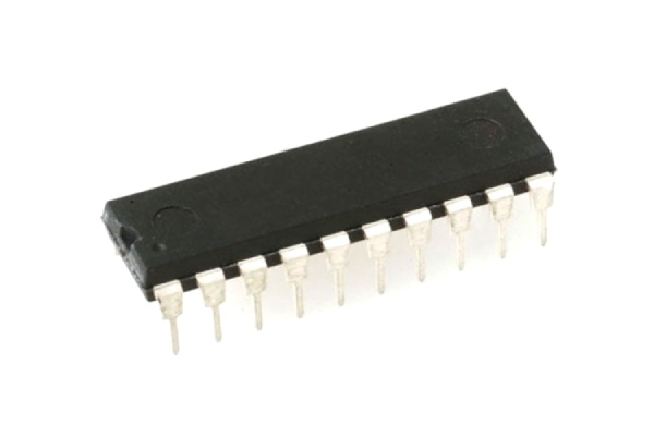
Available Packages for MG82F6D17
SSOP-20, TSSOP-20, QFN-20, PDIP-20
How to use A MG82F6D17 Microcontroller?
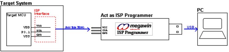
There are mainly two ways to program an MG82F6D17 or most of the megawin controllers. The first one is to use their official Megawin ISP Programmer or another way to use this device is to flash the device via UART. The official tool looks like the image below.
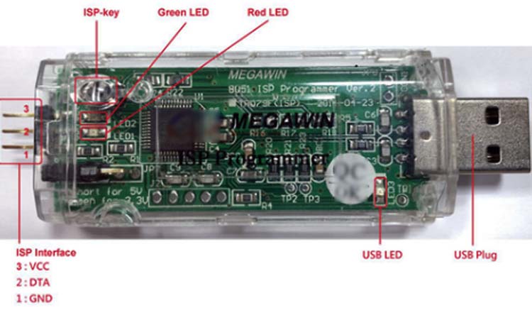
You connect VCC to VCC, Gnd to Gnd, and the Data pin goes to the P3.1 pin for most of the Megawin controller, and you are done. This configuration is very similar to STM8 Controllers.
The other way to program this device is to use a USB to UART Converters like FTDI to connect and power the device and connect RX and TX accordingly to program the device. All program and flashing-related documentation are available on the Megawin official website.
Most of the popular microcontroller manufacturers out there have their own IDE (Integrated Development Environment) to work with the microcontroller but this Megawin device does not have that because it's new. If you want to write your own code and flash it you have to use the Keil IDE and C51 Compiler.
Applications
- Implantable medical devices,
- Remote controls,
- Office machines,
- Appliances,
- Power tools,
- Toys, and other embedded systems
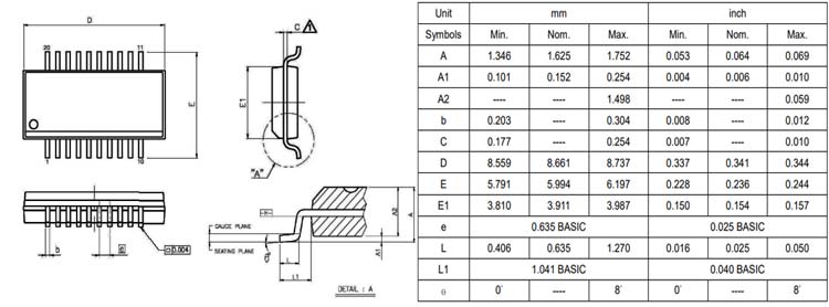
2D Model and Dimensions
If you are designing a PCB or Perf board with this component then the following picture from the Datasheet will be useful to know its package type and dimensions.