MB10F Surface Mount Glass Passivated Bridge Rectifier
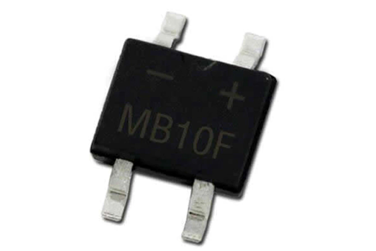
The MB10F is a surface mount glass passivated bridge rectifier from diodes incorporated with a low voltage drop of 1.1V and a forward continuous current of 800mA. It has high efficiency and a high surge current capability of 30A.
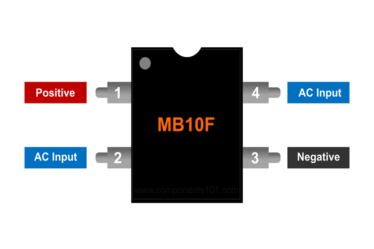
MB10F Pinout Configuration
|
Pin Number |
Pin Name |
Pin Description |
|
1 |
Positive |
Positive of Rectified Output |
|
2 |
AC Input |
AC Input |
|
3 |
Negative |
Negative of Rectified Output |
|
4 |
AC Input |
Ac Input |
Features & Specifications
- Glass Passivated Die Construction
- Miniature Package Saves Space on PC Boards
- Reliable Robust Construction
- Forward Current (IF): 800mA
- Ideal for SMT Manufacturing
- Maximum Forward Voltage (VF): 1.1V (@800mA)
- Max Surge Current: 30A
- Operating Temperature Range: -55°C to + 150°C
- Lead-Free Finish; RoHS Compliant
- Halogen and Antimony Free. “Green” Device
MB10F Alternatives
DF10
Note: Complete technical details about this IC can be found in the MB10F datasheet, linked at the end of the page.
General Description of MB10F Bridge Rectifier
The MB10F is a bridge rectifier diode in a small surface-mount package and is commonly used for single-phase applications. The maximum input AC voltage of this IC is 700V hence, can be used for a broad range of applications. The maximum DC current that this IC can handle is 800mA. This IC has a reverse breakdown voltage of 1000V and a low forward voltage drop of 1.1V. If you are looking for a compact IC for rectification application this can be a good choice.
How to use MB10F Bridge Rectifier
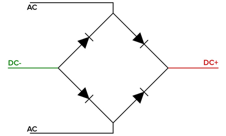
Using the MB-10F is relatively simple. As the name suggests the IC is a full bridge rectifier that is nothing but a construction of four diodes that is shown below.
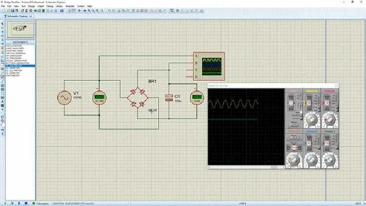
The simulated circuit below shows how a bridge rectifier behaves when we apply AC voltage to the AC side of the rectifier, and for the DC side, we have put a smoothing capacitor to rectify the pulsed DC to a smoother out DC signal. The output DC voltage of the IC can be calculated using the formula
DC Out = (√2×VRMS) – 1.1 Volts
Where VRMS is the input RMS voltage and -1.1V is for the voltage drop that appears across each diode path during rectification. Though in our simulation we will not get that because in the simulation all devices are ideal devices.
Applications
- AC to DC converters
- SMPS
- Consumer Grade LED lights
- Wall Adapters
- Battery Chargers
- Home appliances
- Office equipment
- Telecommunication applications
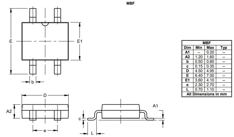
2D Model and Dimensions
If you are designing a PCB or Perf board with this component then the following picture from the MB10F datasheet will be useful to know its package type and dimensions.