MAX30100 - Heart Rate Oxygen Pulse Sensor
Description of MAX30100
MAX30100 is a multipurpose sensor used for multiple applications. It is a heart rate monitoring sensor along with a pulse oximeter. The sensor comprises two Light Emitting Diodes, a photodetector, and a series of low noise signal processing devices to detect heart rate and to perform pulse oximetry.
Features of MAX03100
Here are some of the features and specifications of the MAX03100 Heart Rate Oxygen pulse sensor.
- Operating Voltage - 1.8V to 3.3V
- Input Current - 20mA
- Integrated Ambient Light Cancellation
- High Sample Rate Capability
- Fast Data Output Capability
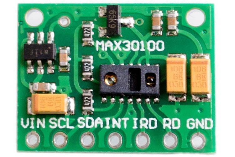
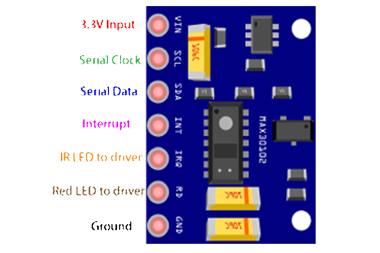
Pin Configuration of MAX30100 Oximeter Module
Below is the pin configuration of the MAX30100 module. It is a 7 pin sensor module with an enabled I2C communication protocol to interact with the microcontroller.
|
Pin Type |
Pin Function |
|
VIN |
Voltage Input |
|
SCL |
I2C - Serial Clock |
|
SDA |
I2C - Serial Data |
|
INT |
Active low interrupt |
|
IRD |
IR LED Cathode and LED Driver Connection Point(Leave floating in the circuit) |
|
RD |
Red LED Cathode and LED Driver Connection Point(Leave floating in the circuit) |
|
GND |
Ground pin |
Note: There are two module versions of the MAX30100 sensor module. The one which we have showcased is the 7-pin version, whereas there is a 5-pin version as well which does not have IRQ and RD pin.
The 5-pin module is considered to be more accurate as the circuitry for the module is on the other side of the sensor.
Alternatives for MAX30100
Pulse 3+, Proto Central AFE4490, ROHM BH1792GLC, FSH 7060
Equivalent for MAX30100
MAX30102
Note: More technical information can be found in the MAX30100 Datasheet linked at the bottom of this page.
Working of the MAX30100 Oximeter
Working of an oximeter:
The sensor consists of a pair of Light-emitting diode which emits monochromatic red light at a wavelength of 660nm and infrared light at a wavelength of 940 nm. These wavelengths are particularly chosen as at this wavelength oxygenated and deoxygenated hemoglobin have very different absorption properties. As shown in the graph below, it can be seen that there is a difference between HbO2(oxygenated Hb) and Hb(deoxygenated Hb) when subjected to these specific wavelengths.
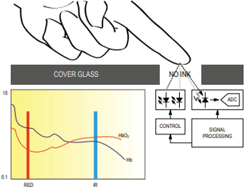
Sensor part:
There are two parts to the sensor, an emitting diode, and a photoreceiver. As the photodiode emits the light, it falls over the finger which has to be placed steadily. The light emitted gets absorbed by the oxygenated blood and the rest of the light is reflected through the finger and falls over the detector whose output data is then processed and read through a microcontroller.
Connecting MAX 30100 Module to a Microcontroller
I showed the connections from MAX30100 to the Arduino microcontroller below. The pulse oximeter uses an I2C communication protocol in order to communicate with the microcontroller. The connections are pretty simple and you can easily make your own Ardunio oximeter.
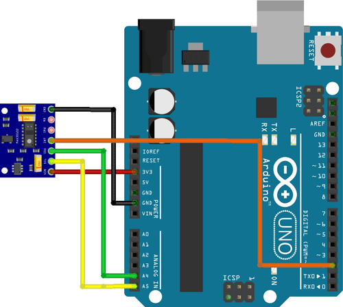
Vin is connected to the 3.3V port of Arduino since the operating voltage of the module is 1.8V-3.3V. The ground terminal of the oximeter is connected to the ground of the Arduino. As part of the communication protocol, two pins which are the SCL and SDA are connected to the Arduino’s A5 and A4 pins, respectively. The INT pin on the module is also connected to the microcontroller’s Digital Pin 2 to check if the heartbeat is captured properly.
Functional Block and the Circuit Diagram of MAX30100 Module
Below is the functional block for the MAX30100 module. The module consists of two LEDs (IR and RED) both of specific wavelengths, along with a photodetector to detect the received light.
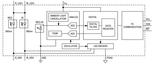
The output from the photodiode is sent to the analog-to-digital converter from which the digital data is sent from a filter to the digital data register. The data can be collected from the register and can be sent to the microcontroller following the I2C communication protocol.
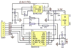
The image above showcases the internal circuitry of the MAX30100 module and can be used as a reference circuit while designing your own custom module.
Applications of MAX30100
Here are some of the applications where MAX30100 can be used:
- Medical Oxygen measurement devices
- Wearable Devices
- Fitness Assistant systems
2D Model of MAX30100
Below is the 2D model of the MAX30100 sensor module. It can be followed while designing custom footprints for the sensor.
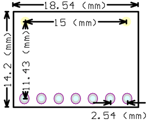
Note: All the dimensions are in millimeters.