LM555 Vs NE555

The alphabet prefixes in front of the part numbers of ICs are often taken for granted, since all they do is represent the manufacturer of the IC (although not in all cases) – but this is not always so. While certain chips have a lot of second sources with the same part numbers and/or prefixes, there oftentimes subtle differences to each of these parts, which arise from optimizations and changes made by each manufacturer. A good example of this is the NE555 timer IC, originally from Signetics, and the LM555, which was initially second sourced from National Semiconductor. In this article, we will first compare NE555 vs LM55 IC and see how improvements were made on to the LM555 from the early NE555.
Deep dive into NE555 and LM555
Since, most second-source ICs are marketed as ‘plug-in’ replacements for the original, little is done to draw attention to the fact that the IC’s internals might have been modified a bit, but luckily, manufacturers add a (simplified) schematic diagram to the datasheets, which we will take a look at.

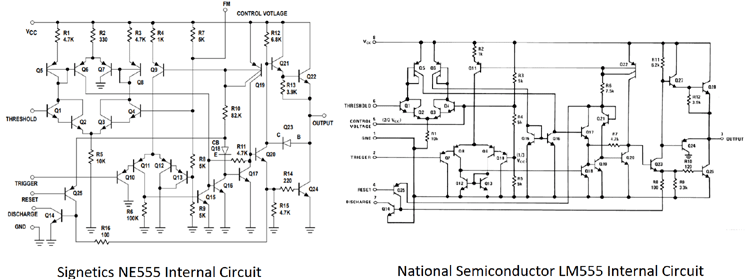
FIG.1 INTERNAL CIRCUIT DIAGRAMS FOR THE NE555 AND LM555
The usage of current mirror active loads in the LM555 is one of the most noticeable difference between the two ICs.
Behavioral Changes
Despite being ‘pin’ compatible, the changes to the LM555 make the circuit behave a lot different, compared to the NE555.
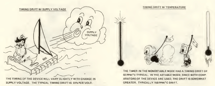
As we understood from the internal diagram, in LM55 we have active loads in place of fixed resistors. One of the prime benefit through this switch from resistors to active loads is that it reduces the dependence of output timing on temperature and supply voltage.
This is highlighted in the original NE555 datasheet from Signetics.

FIG.2 NE555 DRIFT WITH TEMPERATURE AND TIME
Another difference is that in the original NE555, the trigger signal is given more priority, whereas in the LM555, the threshold signal is given more priority.
Generally, in a 555 timer, the output goes high when pin 2 (trigger) goes lower than 1/3VCC, and the output goes low when pin 6 (threshold) goes above 2/3VCC.
In the NE555, if the trigger pin goes low even when the threshold pin is high, the output goes low.
However, in the LM555, the output stays low even when the trigger pin goes low, and it only goes high again when the threshold pin goes low.
There have been reports of additional unwanted pulses on the output of the LM555, which might be due to the different priorities assigned to the threshold and trigger pins.
Table of Major Differences between NE555 and LM555
|
NE555 |
LM555 |
|
Output timing is dependent on temperature and supply voltage |
Output timing is relatively independent of temperature and supply voltage |
|
Trigger pin has a higher priority |
Threshold pin has a higher priority |
Conclusion
Sometimes, assuming that the same part from a different manufacturer is completely ‘pin-compatible’ is wrong since there might be subtle changes and improvements between parts from different manufacturers. It is always best to test chips before the use for a particular application.


