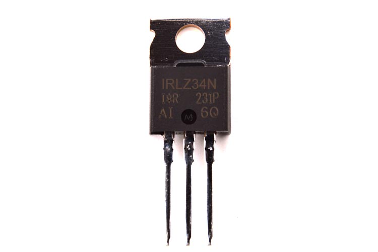
IRLZ34N N-Channel Power MOSFET
The N-channel high power MOSFETs (Metal–Oxide–Semiconductor Field-Effect Transistor) are popular for driving higher voltages and currents from a microcontroller. They have a very low ON resistance (@0.035Ω or 35 milliohm) hence, they dissipate less heat and they usually don’t need a heat sink (as long as the load is less than 2.5 Amps). The IR MOSFET family of power MOSFETs is used for a wide range of devices to support various applications such as DC motors, inverters, SMPS, lighting, load switches as well as battery-powered applications.
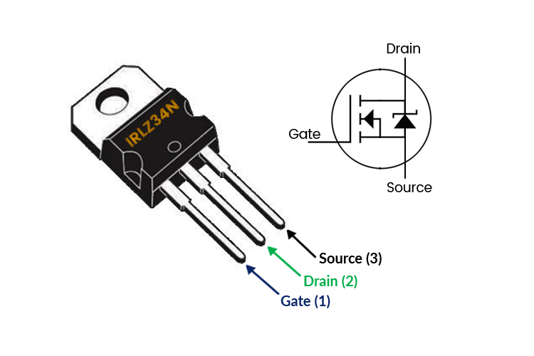
IRLZ34N MOSFET Pinout Configuration
|
Pin Number |
Pin Name |
Pin Description |
|
1 |
Gate |
Controls the biasing of the MOSFET |
|
2 |
Drain |
Current flows in through the Drain |
|
3 |
Source |
Current flows out through the Source and leaves the MOSFET |
Features and Specifications
- Manufacturer: Infineon
- Mounting Style: Through Hole component
- Package/Case: TO-220 case
- Height: 15.65 mm
- Length: 10 mm
- Width: 4.4 mm
- Rise Time: 100 ns
- Fall Time: 29 ns
- Transistor Polarity: N-Channel
- Channel Mode: Enhancement
- Operating Temperature Range: - 550 C to + 1750 C
- Drain-Source Breakdown Voltage (VDSS) = 55V
- Continuous Drain Current (Id) = 30A
- On - Drain-Source Resistance (Rds): 0.035Ω
- Power Dissipation (Pd): 68 W
- Drain-to-Source Breakdown Voltage: 55 V
- Maximum Gate-to-Source Voltage: ±16 V
IRLZ34N Equivalent MOSFETS
IRLZ44Z, IRLZ44N, IRFB3607G, IRFB3207Z, IRF3205Z, IRF1407, IRFB4310ZG, IRFB4510G, IRF3710, IRF1407, IRF1010EZ, IRFB4321, IRFZ44V, IRFB4410, etc.
IRLZ34N MOSFETs Working (n-channel, Enhancement type)
To test MOSFETs, (enhancement type) let’s briefly understand what’s going on internally. Now MOSFETs are commonly used as switches. A voltage is applied to the Gate pin, this turns ON the Drain to Source path and hence it acts as a switch. Now, this is better than mechanical switches in some cases because there’s no moving part. The Gate is insulated from the Drain and Source and it acts as a very small capacitor with positive voltage on the Gate with respect to the Source turns ON the channel and the device conducts. When the Gate-Source voltage is dropped to zero, then the device turns OFF.
How to use DMM to test the ON and OFF state of the MOSFET
Now, to test the MOSFET, set the DMM to the diode feature. To test the MOSFET in the OFF state, leave the Gate without applying any voltage on it and check the connection between Drain and the Source. So, connect the Negative probe of the DMM to the Source and the Positive lead to the Drain. And the DMM should show OL (overload, it means that there’s an open circuit). Now, we should give a small voltage to the Gate pin and watch it act as a small capacitor. To do that, take the positive probe of the DMM and momentarily touch the Gate pin and connect the positive probe back to the Drain. Now we can see that we’ve a short circuit (you should be able to hear the buzzer beep indicating short circuit). This means the Gate is charged up and the MOSFET is in ON state. To put the MOSFET back to the OFF state, we need to discharge the Gate. Since it’s a small voltage, just touch the Gate and Source together with a finger, it’ll discharge and the MOSFET turns OFF.
How to use IRLZ34N as a Switch
We can use MOSFET as a Switch by applying a voltage to the Gate terminal. As this is “FET” the current flow between Drain and Source is controlled by the voltage applied at the Gate terminal. MOSFETs can be used where there’s a need for switching signal, regulation, driving motor, etc.
The above circuit shows how IRLZ34N is being used as a switch. As mentioned earlier, we can turn ON the MOSFET by applying a voltage at the Gate terminal, and by discharging the Gate terminal we can turn OFF the MOSFET.
Applications
- Regulators
- Uninterrupted Power Supplies
- Motor drives
- Used as switching electronic signals
- Used in battery management
- Relay drivers
- Electric Power Steering (EPS)
- DC-DC converters and DC-AC converters
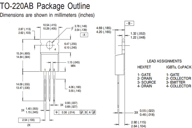
2D Model and Dimensions
If you are designing a PCB or Perf board with this component then the following picture from the IRLZ34N Datasheet will be useful to know its package type and dimensions.