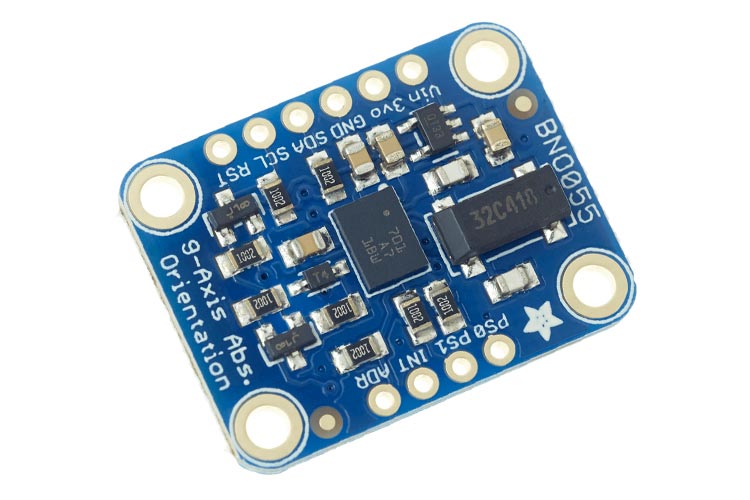
BNO055 - Intelligent 9-axis Absolute Orientation Sensor Module
The BNO055 is a System in Package (SiP), integrating a triaxial 14-bit accelerometer, a triaxial 16-bit gyroscope with a range of ±2000 degrees per second, a triaxial geomagnetic sensor, and a 32-bit Cortex M0+ Microcontroller running Bosch Sensortec sensor fusion software, in a single package.
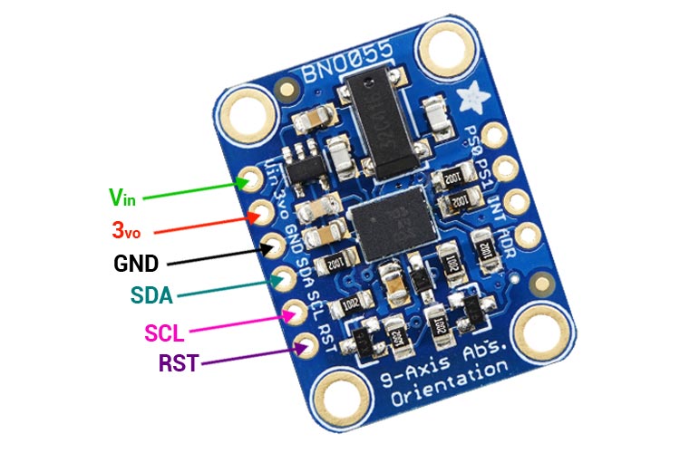
BNO055 Sensor Module Pinout Configuration
|
Pin Number |
Pin Name |
Description |
|
1 |
Vin |
3.3-5.0V power supply input |
|
2 |
3Vo |
3.3V output from the on-board linear voltage regulator, you can grab up to about 50mA as necessary |
|
3 |
GND |
The common/GND pin for power and logic |
|
4 |
SDA |
I2C data pin, connect to your microcontroller’s I2C data line. This pin can be used with 3V or 5V logic, and there's a 10K pullup on this pin. |
|
5 |
SCL |
I2C clock pin, connect to your microcontroller's I2C clock line. This pin can be used with 3V or 5V logic, and there's a 10K pullup on this pin |
|
6 |
RST |
Hardware reset pin. Set this pin low then high to cause a reset on the sensor. This pin is 5V safe. |
Features and Specifications
- 3 sensors in one device (an triaxial 16bit gyroscope, a triaxial 14 bit accelerometer, and a full performance geomagnetic sensor)
- Intelligent Power Management: normal, low power, and suspend mode available
- Outputs fused sensor data
- Small package (LGA package 28 pins)
- Common voltage supplies (VDD voltage range: 2.4V to 3.6V )
- Digital interface (HID-I2C (Windows 8 compatible), I²C, UART)
- Consumer electronics suite (MSL1, RoHS compliant, halogen-free Operating temperature: -40°C ... +85°C)
BNO055 Alternative Sensors
BMX055, MPU9250
Note: More technical specifications about BNO055 Sensor can be found in the BNO055 datasheet attached at the end of this page.
General Description of BNO055 Module
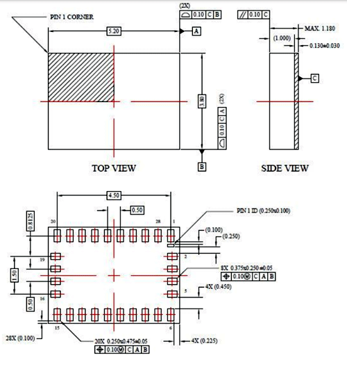
The BNO055 is a System in Package (SiP), integrating a triaxial 14-bit accelerometer, a triaxial 16-bit gyroscope with a range of ±2000 degrees per second, a triaxial geomagnetic sensor, and a 32-bit cortex M0+ microcontroller running Bosch Sensortec sensor fusion software, in a single package. The corresponding chip-sets are integrated into one single 28-pin LGA 3.8mm x 5.2mm x 1.1 mm housing. For optimum system integration, the BNO055 is equipped with digital bidirectional I2C and UART interfaces. The I2C interface can be programmed to run with the HID-I2C protocol turning the BNO055 into a plug-and-play sensor hub solution for devices running the Windows 8.0 or 8.1 operating system.
This chip can also be found in a prebuilt module, made by Adafruit industries. As this module comes with a generic I2C interface, communication with different microcontrollers and FPGA becomes easier. If you are using the module all the necessary passive hardware requirements are pre-built onto the board, but if you are placing this chip directly onto the PCB, certain design sections should be for smooth operation.
Different Communication Configurations of BNO055 Module
This is a very versatile IC and it can communicate with the master device in three configurations, the schematic for each is shown below.
- I2C Configuration
- UART Configuration
- HID Configuration
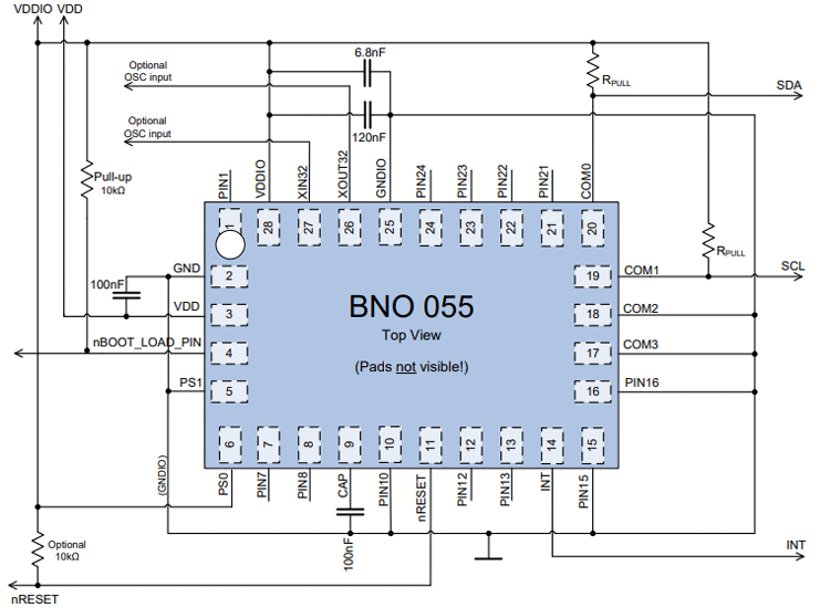
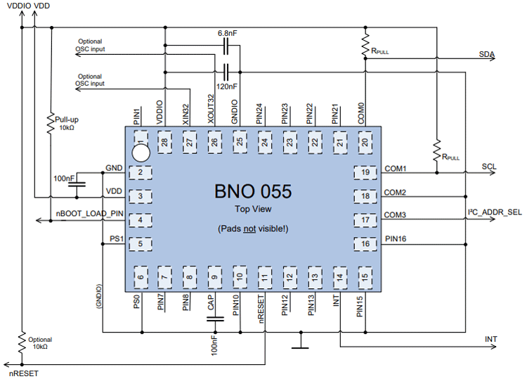
I2C Configuration Schematic for BNO055 Module
The I²C bus uses SCL (= SCx pin, serial clock) and SDA (= SDx pin, serial data input, and output) signal lines. Both lines are connected to VDDIO externally via pull-up resistors so that they are pulled high when the bus is free.
UART Configuration Schematic for BNO055 Module
The BNO055 supports UART interface with the following settings: 115200 bps, 8N1 (8 data bits, no parity bit, one stop bit). The maximum length support for read and write is 128 Byte. The packet structure for register read and write is described below.
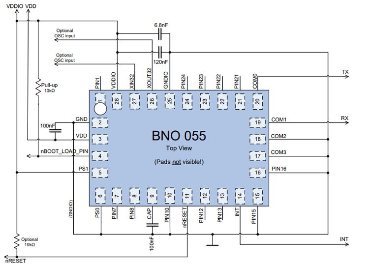
HID Configuration Schematic for BNO055 Module
The I2C interface can be programmed to run with the HID-I2C protocol turning the BNO055 into a plug-and-play sensor hub solution for devices running the Windows 8.0 or 8.1 operating system
Applications
- Navigation
- Robotics
- Fitness and well-being
- Augmented reality
- Context awareness
- Tablets and ultrabooks
2D Model and Dimensions
The 2D model for the IC is shown below, if you are designing a compact PCB with this the measurement below can come in handy, more info on the dimension can be found in the datasheet of the product linked in the description.
