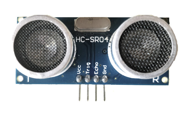
HC-SR04 Ultrasonic Sensor
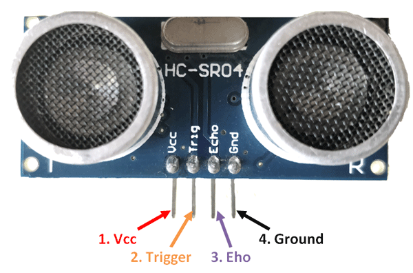
Ultrasonic Sensor Pinout Configuration
|
Pin Number |
Pin Name |
Description |
|
1 |
Vcc |
The Vcc pin powers the sensor, typically with +5V |
|
2 |
Trigger |
Trigger pin is an Input pin. This pin has to be kept high for 10us to initialize measurement by sending US wave. |
|
3 |
Echo |
Echo pin is an Output pin. This pin goes high for a period of time which will be equal to the time taken for the US wave to return back to the sensor. |
|
4 |
Ground |
This pin is connected to the Ground of the system. |
HC-SR04 Sensor Features
- Operating voltage: +5V
- Theoretical Measuring Distance: 2cm to 450cm
- Practical Measuring Distance: 2cm to 80cm
- Accuracy: 3mm
- Measuring angle covered: <15°
- Operating Current: <15mA
- Operating Frequency: 40Hz
More details can be found in the HC-SR04 ultrasonic sensor datasheet attached at the bottom of this article.
Equivalent distance measuring Sensors
US transmitter Receiver pair, IR sensor module, IR sensor pair, IR Analog distance sensor,
HC-SR04 Ultrasonic Sensor - Working
As shown above the HC-SR04 Ultrasonic (US) sensor is a 4 pin module, whose pin names are Vcc, Trigger, Echo and Ground respectively. This sensor is a very popular sensor used in many applications where measuring distance or sensing objects are required. The module has two eyes like projects in the front which forms the Ultrasonic transmitter and Receiver. The sensor works with the simple high school formula that
Distance = Speed × Time
The Ultrasonic transmitter transmits an ultrasonic wave, this wave travels in air and when it gets objected by any material it gets reflected back toward the sensor this reflected wave is observed by the Ultrasonic receiver module as shown in the picture below
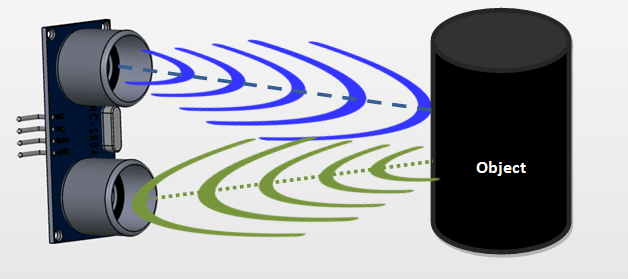
Now, to calculate the distance using the above formulae, we should know the Speed and time. Since we are using the Ultrasonic wave we know the universal speed of US wave at room conditions which is 330m/s. The circuitry inbuilt on the module will calculate the time taken for the US wave to come back and turns on the echo pin high for that same particular amount of time, this way we can also know the time taken. Now simply calculate the distance using a microcontroller or microprocessor.
How to use the HC-SR04 Ultrasonic Sensor
HC-SR04 distance sensor is commonly used with both microcontroller and microprocessor platforms like Arduino, ARM, PIC, Raspberry Pie etc. The following guide is universally since it has to be followed irrespective of the type of computational device used.
Power the Sensor using a regulated +5V through the Vcc ad Ground pins of the sensor. The current consumed by the sensor is less than 15mA and hence can be directly powered by the on board 5V pins (If available). The Trigger and the Echo pins are both I/O pins and hence they can be connected to I/O pins of the microcontroller. To start the measurement, the trigger pin has to be made high for 10uS and then turned off. This action will trigger an ultrasonic wave at frequency of 40Hz from the transmitter and the receiver will wait for the wave to return. Once the wave is returned after it getting reflected by any object the Echo pin goes high for a particular amount of time which will be equal to the time taken for the wave to return back to the sensor.
The amount of time during which the Echo pin stays high is measured by the MCU/MPU as it gives the information about the time taken for the wave to return back to the Sensor. Using this information the distance is measured as explained in the above heading.
Applications
- Used to avoid and detect obstacles with robots like biped robot, obstacle avoider robot, path finding robot etc.
- Used to measure the distance within a wide range of 2cm to 400cm
- Can be used to map the objects surrounding the sensor by rotating it
- Depth of certain places like wells, pits etc can be measured since the waves can penetrate through water
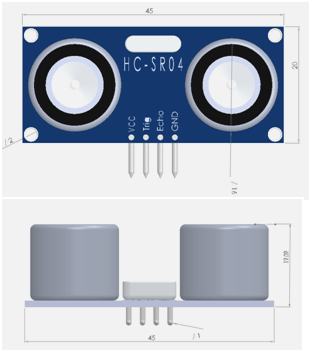
2D model of the component


Ultrasonic sensors
What is the input and output of ultrasonic sensor?