TP5000 Switching Battery Charger
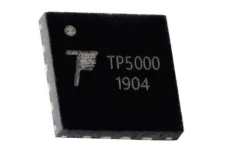
The TP5000 is a single-cell lithium battery charger. Unlike other chargers, the TP5000 is a switching charger, meaning it can supply higher currents while being efficient at the same time. It also has several useful features like temperature, overcurrent, and undervoltage, while also having programmable charging currents.
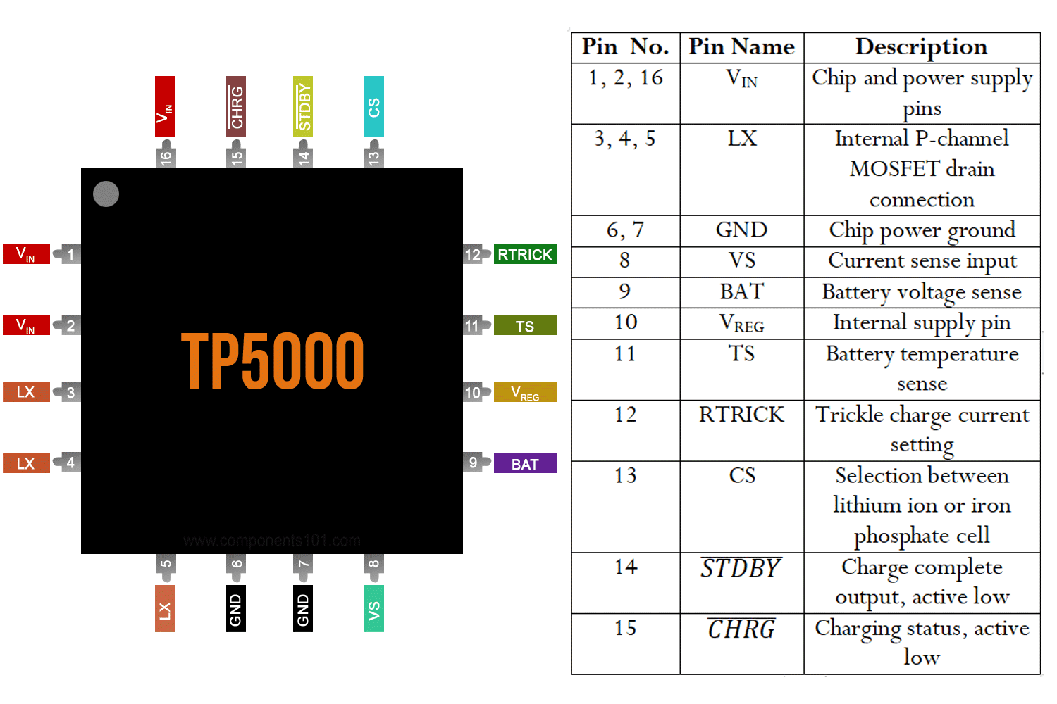
TP5000 Pinout Description
|
Pin Number |
Pin Name |
Description |
|
1, 2, 16 |
VIN |
Chip and power supply pins |
|
3, 4, 5 |
LX |
Internal P-channel MOSFET drain connection |
|
6, 7 |
GND |
Chip power ground |
|
8 |
VS |
Current sense input |
|
9 |
BAT |
Battery voltage sense |
|
10 |
VREG |
Internal supply pin |
|
11 |
TS |
Battery temperature sense |
|
12 |
RTRICK |
Trickle charge current setting |
|
13 |
CS |
Selection between lithium ion or iron phosphate cell |
|
14 |
|
Charge complete output, active low |
|
15 |
|
Charging status, active low |


Features and Specifications
- Single Li-ion or Li-FePo battery charger
- Built-in power MOSFET
- 0.1A to 2A programmable charge current with 10% to 100% precharge current
- Input voltage max. 9V
- Overtemperature, overcurrent, and undervoltage protection
- QFN16 package
Note: Complete technical details can be found in the TP5000 datasheet linked at the end of this page.
Other Battery Chargers
How To Use TP5000
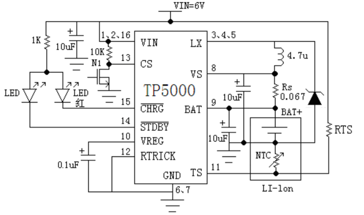
FIG.- TP5000 TYPICAL APPLICATION CIRCUIT
Lithium batteries of any kind are fussy with regards to charging requirements – just connecting them up to the right voltage will not work. They have a maximum charging current specified in terms of battery capacity. There is also the requirement of temperature monitoring since heat negatively affects battery health. The TP5000 integrated battery charging IC takes care of most of these functions. It is based on a switching buck converter, meaning it can handle higher currents, while at the same time being efficient and not heating up as much as a linear IC would. The switching frequency of 800kHz enables the use of a very small inductor, between 2.2uH and 10uH.
The IC is designed to charge both lithium-ion and lithium iron phosphate batteries. They have different nominal voltages and hence voltage requirements. This can be accounted for by driving the pin CS correctly. If li-po charging is desired, the pin can be pulled low directly using an open-drain output. If li-fe-po charging is required, a 10K resistor should be added between VIN and CS.
Charging current is set by selecting the value of the shunt resistor connected between VS and BAT. The current limit threshold is 100mV, so the required shunt resistance is 0.1V/Iout. For a maximum of 2A out, a shunt resistance of 50mΩ is needed. Trickle charge is a percentage of the maximum charging current. Shorting the RTRICK pin to ground sets trickle current to 10% of the charging current, and leaving it floating sets it to 100%. 320KΩ set it to 50%.
LEDs can be connected to the STDBY and CHRG pins. The datasheet recommends a green LED for STDBY and a red LED for CHRG. When the red LED is lit, the battery is in the charging state. When the green LED is lit, the battery is fully charged. Both LEDs off indicate an error such as overtemperature or undervoltage. When the LEDs flash alternatively, no battery was detected.
The TS pin is meant to be connected to a voltage divider, the bottom leg of which is an NTC. The threshold is set to 80% of VIN, so the resistors must be selected accordingly.
Applications
- Tablet computers, mobile phones, MP3 players
- Electrical tools
- White LED driver
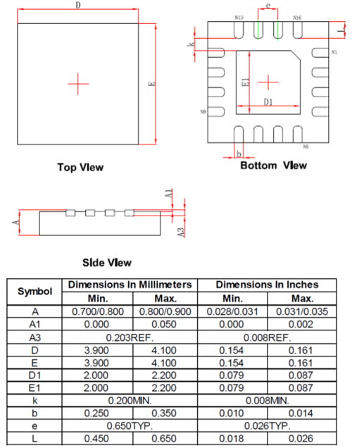
2D Model and Dimensions