TM1637- Grove 4 Digit Display Module
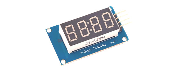
TM1637 DISPLAY module is used for displaying numbers. The module consists of four 7- segment displays working together. The module working is based on ‘TM1637’ IC present internally and hence the name ‘TM1637 display’.
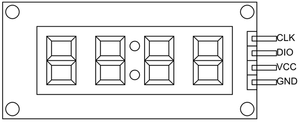
TM1637 Pin Configuration
TM1637 DISPLAY is a four terminal device. We will describe function of each pin below.
|
Pin Name |
Description |
|
VCC |
Connected to power source. |
|
GND |
Connected to ground. |
|
DIO |
Data Input/output pin |
|
CLK |
Clock pin |
TM1637 Display Features and Specifications
- Two wire interface
- Eight adjustable luminance levels
- Grove compatible interface (3.3V/5V)
- Four alpha-numeric digits
- Potable size
- Operating voltage: 3.3V – 5.5V
- Operating current consumption: 80mA
- Operating temperature: -10ºC to +80ºC
Why to use TM1637 Display Module?
There are many reasons why TM1637 DISPLAY is preferred a few are stated below
- The module can be interfaced to any system using only two pins. This is the main reason the module is preferred over other module. The characters to be displayed on the screen can be sent to module using only two pins. With that we can save many I/O pins of system which can be used for other important tasks.
- Another main reason TM1637 display is preferred is because of its low cost. Although there are other display modules present in the market they cost more.
- The module design is robust so it can sustain in tough environments and still can perform its function for a long time.
- The module consumes low power and can be installed in mobile applications.
- There are many pre-written programs for the module which helps in easy installation.
How to use TM1637 Display Module?
As mentioned earlier the module communication can only be done using the two pins ‘DIO’ and ’CLK’ respectively. The data is sent to the module or received from the module though these two pins. So the characters to be displayed are sent in the form of serial data through this interface. A typical circuit diagram of display module interface to a controller is shown below.
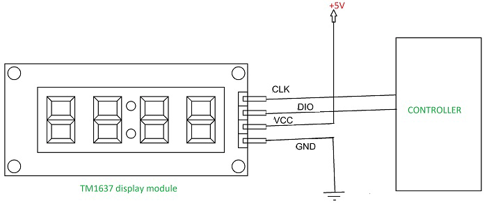
The module can work on +5V regulated power and any higher voltage may lead to permanent damage. The interface is established as shown in figure. All you need to do is connect DIO and CLK to any of GPIO (General Purpose Input Output) pins of controller and establish serial data exchange through programming.
This serial data transmission between controller and module is really complex. So we will be using libraries which are written for the module to help with data transmission. All you need to do is download these libraries which are available in various websites and call them in application programs. Once the header file is included, the controller performs the communication by itself and required display characters will be sent to module.
The TM1637 IC on the module receives the serial data sent by the controller. The chip drives the 4 display segments according to the code. The segments light up to display the desired character.
Applications
- Power units
- Time display
- Stop watch and counters
- Robotics
- Servers
- Computer Peripherals
- GPS
- Utility power meters
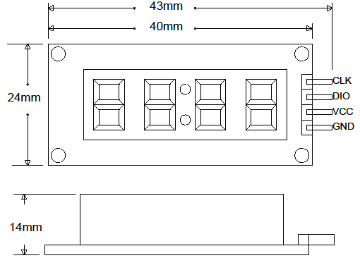
2D-Model
Measurements in millimeter