MPU9250 9-DOF MEMS Sensor Module
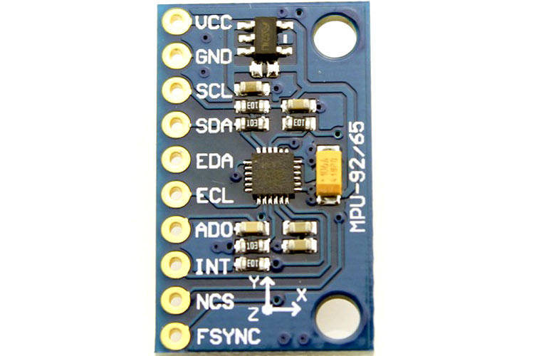
The MPU9250 integrates an accelerometer, a gyroscope, and a magnetometer into a single small package. The MPU9250 has the needed pull-up and pull-down resistors for the I2C/SPI lines and the address select and the frame synchronization pin.
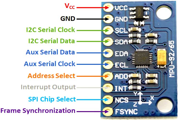
MPU9250 Module Pinout
|
Pin Number |
Pin Name |
Description |
|
1 |
VCC |
Power Supply |
|
2 |
GND |
Ground Reference |
|
3 |
SCL |
I2C Serial Clock |
|
4 |
SDA |
I2C Serial Data |
|
5 |
EDA |
Auxiliary Serial Data |
|
6 |
ECL |
Auxiliary Serial Clock |
|
7 |
AD0 |
I2C/SPI Address Select |
|
8 |
INT |
Interrupt |
|
9 |
NCS |
SPI Chip Select |
|
10 |
FSYNC |
Frame Synchronization |
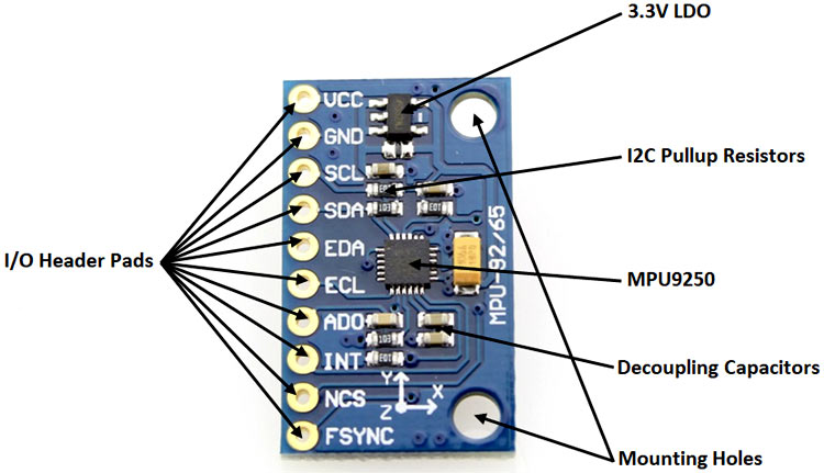
Components Present on MPU9250 Module
Following are the major components present on the MPU9250 module, which will be described later in the article.
- MPU9250
- Decoupling capacitors
- Pullup resistors
- LDO regulator
MPU9250 Specifications
- Supply Voltage – 5V (typical)
- Supply Current – 4mA (typical)
- Accelerometer Range - ±2g, ±4g, ±8g, ±16g
- Gyroscope Range - ±250°/second, ±500°/second, ±1000°/second, ±2000°/second
- Magnetometer range - ±4800uT
- I2C, SPI, and Auxiliary I2C
Note: Complete technical details can be found in the MPU9250 Datasheet linked at the bottom of this page.
Alternate Modules
Understanding the MPU9250 Module
The MPU9250 integrates an accelerometer, a gyroscope, and a magnetometer into a single small package. The reason it is so small is that it uses Micro Electro Mechanical Systems (MEMS) – small mechanical components are made directly on the silicon die and are integrated with the electronic components to make a functional sensor.
The module has a built-in LDO regulator, which supplied the MPU9250 with the 3.3V it needs. The LDO cannot handle very high voltages, and it is best powered with 5V. The module also has integrated pullup resistors for the I2C lines.
Header pins are provided to break out all the important pins of the IC so it can easily be connected to a breadboard. Mounting holes are provided to facilitate integration into a project.
Internal Circuit Diagram for MPU9250 Module
The circuit on the board is as follows:
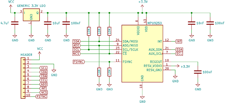
The circuit consists of a low dropout (LDO) linear regulator, which drops the supply voltage (typically 5V) to the 3.3V needed by MPU9250. Due to the small size and limited power dissipation, the LDOs on the board cannot handle a very high voltage, so it is best to power them from 5V. The module also has the needed decoupling capacitors for the LDO.
The MPU9250 has the needed pullup and pulldown resistors for the I2C/SPI lines and the address select and the frame synchronization pin. Since the I2C pull-up values are high, to enhance speed, additional external pullups of a lower value can be added. Adequate decoupling for the various power pins of the chip is also provided.
All the important pins necessary to power and communicate with the sensor have been broken out into a 10-pin header footprint.
How to use the MPU9250 Module
The MPU9250 module can communicate with a microcontroller either through the I2C or the SPI protocol. SPI is recommended for higher speeds, while I2C takes up less pins but at reduced speeds. The module can be connected to a microcontroller as shown in the diagram below.
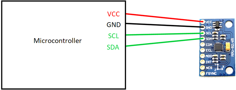
Several Arduino libraries are available which makes usage easier.
MPU9250 Module Basic Troubleshooting
- If the module is not powered up:
- Check the power connection
- Make sure the input voltage is higher than the output voltage plus the minimum dropout voltage of the LDO
- Check if the connections are reversed
- If the module is not communicating with the microcontroller:
- Check if the data pins have been connected correctly
- Check if the correct protocol is being used
- Check if the correct clock speed is being used
MPU9250 Module Applications
- Motion tracking
- Drones
- GPS systems
- Model aircraft and rockets
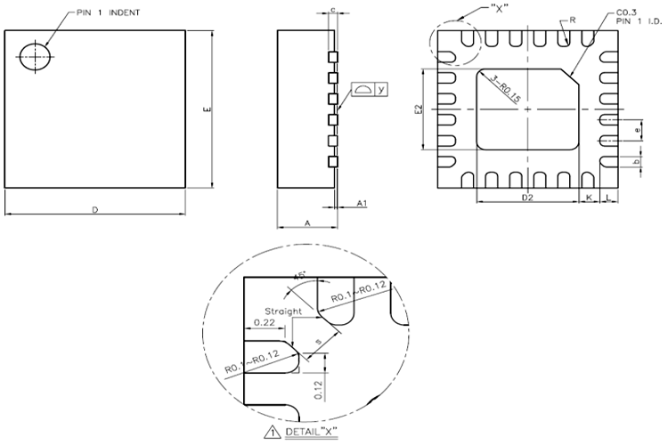
2D Model of The Module
The dimensions of the MPU9250 module are given below to help you with selecting the right PCB footprint for MPU9250.