MPF102 N-Channel JFET
The MPF102 JFET is a popular N-Channel JFET that is commonly used in low power amplifier circuits. The JFET is no longer in production and finding it might be difficult. So they are not recommended for new designs.
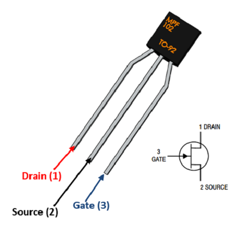
Pin Configuration
|
Pin Number |
Pin Name |
Description |
|
1 |
Drain |
Current flows in through Drain pin |
|
2 |
Source |
Controls the biasing of FET |
|
3 |
Gate |
Current flows out through Drain, normally connected to ground. |
Features
- General Purpose N-Channel Junction Field Effect Transistor
- Drain-Source voltage (VDS) is 25 V
- Maximum Drain current: 20mA
- Drain-Gate voltage (VDG) is 25V
- Gate-Source Voltage (VGS) is -7.5V
- Gate Current (IG) is 10mA
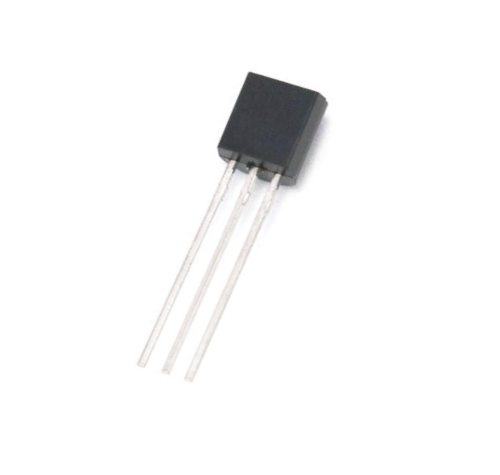
- Available in To-92 Package
Note: Complete Technical Details can be found at the MPF102 datasheet given at the end of this page.
MPF102 Equivalents
NTE457, J113
Brief Description on MPF102
The MPF102 is a JFET that has been used in many amplification circuits because of its low price. The JFET is currently no longer in production but till the demand for it has created many clones in the market. The closest equivalent for NTE457 is the J113 FET.
The clone FETs available in the market does not seem to follow the datasheet strictly. Hence be careful which employing one in your designs. Provided you have the right FET, it can be used in pre-amp circuit to achieve gain of +12dB or high. If you cannot find the supplier, then consider upgrading to NTE457 which his slightly pricy but availability will not be a problem.
How to use MPF102 JFET
A JEFT is considered to be in on state by default that is even if the gate single is not provided (0V) the JFET will allow current to flow from Drain to Source. In order to top the JEFT from conducting a negative gate voltage has to be applied to the gate pin, for the MPF102 it should be typically -7.5V.
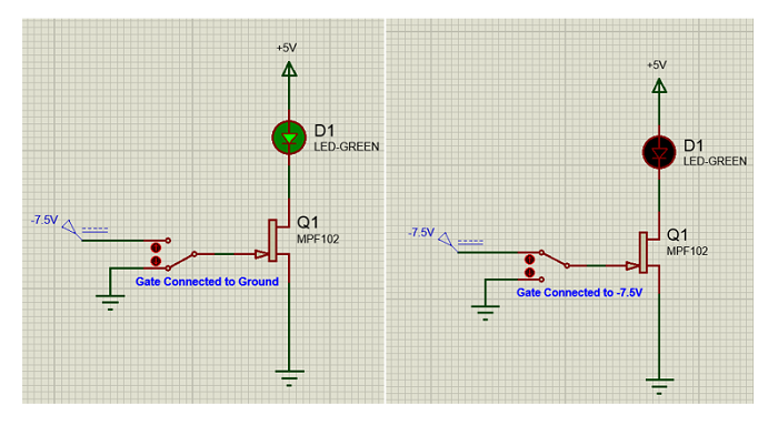
The above two images should how a load (LED) can be toggled using a JFET like MPF102. When the gate pin is grounded, the JFET allows current to flow from drain to source and thus the LED is turned on. When it is biased using -7.5V on the gate pin, the JFET blocks the flow of current between the Drain and Source pin and thus turns off the LED.
Applications
- Amplifier circuits
- Pre-Amp applications
- Audio noise cancelation
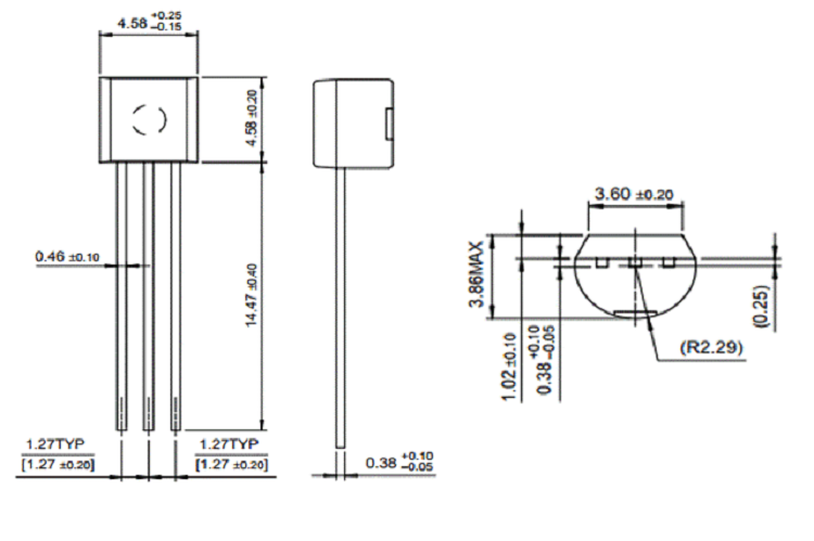
2D model of the component
If you are designing a PCB or Perf board with this component then the following picture from the MPF102 Datasheet will be useful to know its package type and dimensions.