MID400 AC Line Logic Optocoupler
The MID400 is a AC line to logic Power Line Monitor Optocoupler. Meaning, the output of the IC goes low whenever it detects an AC voltage and goes high when no AC voltage is present. This feature can be used to monitor the AC line which will be useful for AC to DC control applications or Relay/solenoid latching applications.
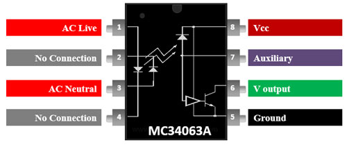
Pin Configuration
|
Pin Number |
Pin Name |
Description |
|
1 |
AC Live |
Alternating Current Live wire is connected to this Pin |
|
2,4 |
No Connection |
Not Used |
|
3 |
AC Neutral |
Alternating Current Neutral wire is connected to this pin |
|
5 |
Ground |
Ground pin of the IC |
|
6 |
V Output |
Open collector Output pin |
|
7 |
Auxiliary |
Can be used to adjust AC voltage sensing and time delay by adding a capacitor to this pin. |
|
8 |
Vcc |
IC Operating Voltage |
Features
- Power Line Monitor IC
- Maximum Working Insulation Voltage: 630Vpeak
- Supply Voltage (Vcc): 7V
- Low level Output current: 20mA
- Low level output voltage: 0.18V
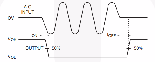
- Turn-on and Turn-off Time: 1ms each
- LED forward voltage drop: 1.5V
- LED on-state input current: ±30mA
- Available in 8-pin DIP and SMD Package.
Alternative Power Line Monitors
UC1903, ACS71020
How to use MID400
The MID400 is an AC Line Monitor IC, the Phase and Neutral wire can be directly connected to the 1st and 3rd pin of the IC through a Resistor (RIN). If the AC voltage is detected the output pin (pin 6) will go low and if not the pin will go high. Both the AC Line and the output voltage is completely isolated by the Optocoupling property of this. A sample application circuit is shown below.
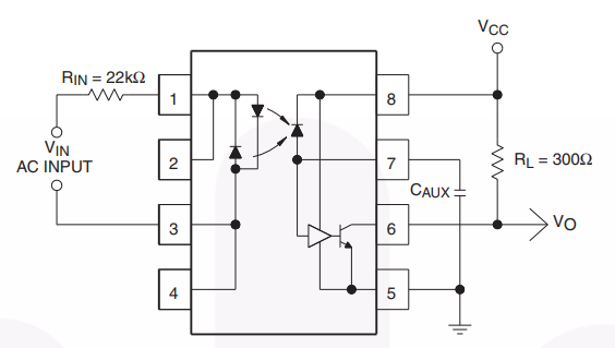
The Resistor Rin is used to limit the current flowing from the Ac line the value of the resistor can be calculated using the below formula
RIN =
Where Vin is the input RMS voltage of the Ac line, Vs if the Forward voltage drop of the internal LED and Iin is the input current required to turn on the internal LED, the value of which can be found at the MID400 datasheet linked below.
The output pin 6 is open collector pin and requires a pull up resistor of 300 ohm tied to the vcc pin as shown above. The capacitor connected to pin 7 can be used to adjust the sensing level and time delay of the output. The below figure should help you understanding the working of output pin.
Applications
- AC to DC Optical Isolation circuit
- AC sensing applications
- Ac to DC converters
- Isolation switch
- Latching circuits
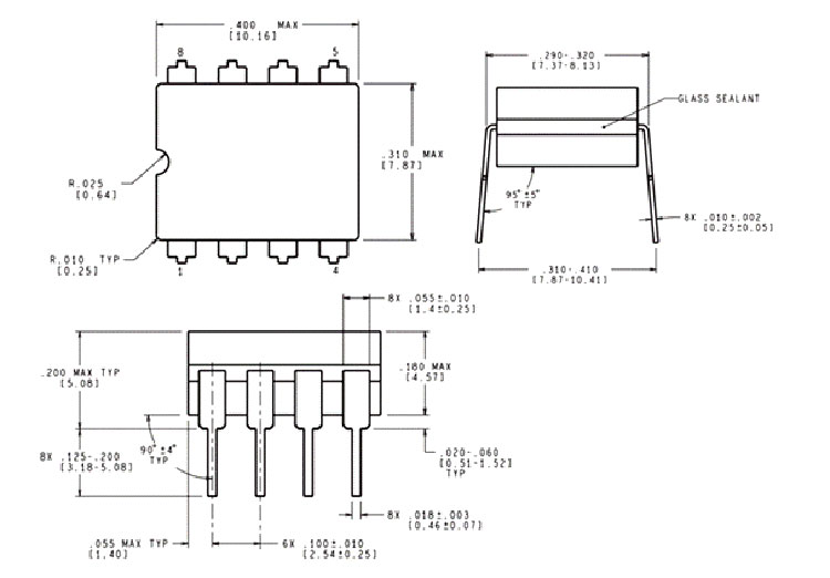
2D Model