Arduino Due
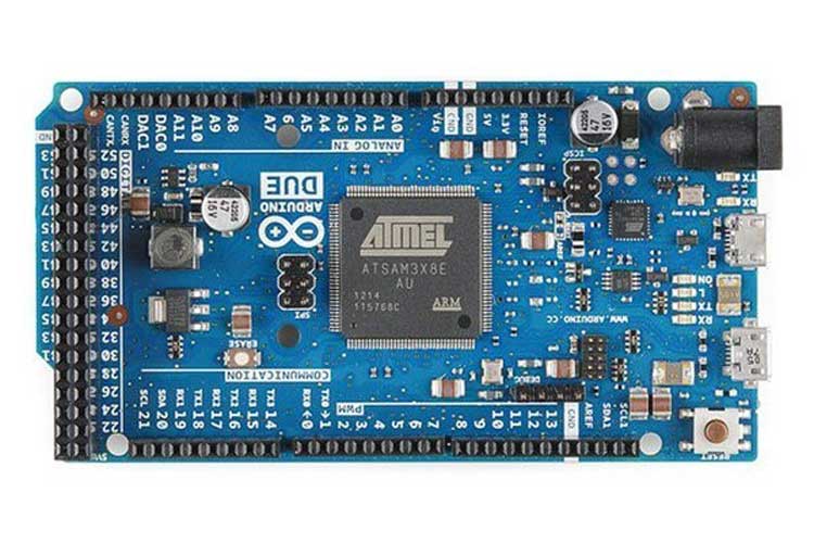
ARDUINO DUE board is one of the most powerful development boards in the ARDUINO series. DUE board not only has tons of features but also has terrific processing speed making it suitable for advanced applications. It could be considered as a professional board considered UNO as a beginner board. DUE board also developed on ARM controller series whereas other boards are developed on ATMEGA controller series.
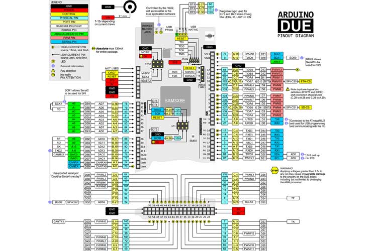
ARDUINO DUE Pinout Configuration
|
PIN GROUP |
PIN NAME |
DESCRIPTION |
|
POWER SOURCE |
+5V, +3.3V, GND and Vin |
+5V - Connected to +5V OR +3.3V- Connected to +3.3V OR Vin- Connected to +7V to +12V GND – Connected to GROUND |
|
COMMUNICATION INTERFACE |
UART Interface(RXD, TXD) x 4 [(0,1),(19,18),(17,16),(15,14)]
SPI Interface(MOSI, MISO, SCK ,RESET) x 1 TWI Interface(SDA, SCL) x 2 [(20,21),(70,71)]
CAN Interface (CANRX , CANTX) x2
SSC Interface (RF, RD, RK, TD, TK, TF) |
UART (Universal Asynchronous Receiver Transmitter) Interface can be used to program PRO MINI SPI (Serial Peripheral Interface) Interface ban be used to program PRO MINI TWI (Two Wire Interface) Interface can be used to connect peripherals.
CAN (Controller Area Network) Interface can be used for communication between controllers SSC(Synchronous Serial Communication) Interface can be used for Audio and Telecom Applications |
|
INPUT OUTPUT PINS |
42 I/O + 12 PWM |
Although these 54 pins have many functions, they can be considered as data I/O pins. |
|
ANALOG to DIGITAL CONVERTER |
ADC0, ADC1, ADC2,…ADC11 |
These channels can be used to input Analog signals. There are of 12 bit resolution. |
|
DIGITAL to ANALOG CONVERTER |
DAC0, DAC1 |
There are two channels which can provide Analog output. They are of 12 bit resolution. |
|
PWM |
PIN2 to PIN13 |
These 12 channels can provide PWM (Pulse Width Modulation) outputs. They are of 8 bit resolution. |
|
RESET |
RESET |
Resets the controller. |
|
EXTERNAL INTERRUPTS |
All I/O |
In DUE board all I/O pins can be used as Interrupts. |
|
TEMPERATURE SENSOR |
Connected to ADC15 internally. |
DUE has internal Temperature sensor which can be programmed to read temperature. |
|
REAL TIME CLOCK |
INTERNAL |
DUE has RTC with CALENDER and ALARM features, which can be enabled internally. |
Technical Specifications
|
Microcontroller |
SAM3X8E – 32 BIT ARM controller |
|
Operating Voltage |
3.3V |
|
Raw Voltage input |
7V to 12V |
|
Maximum current through each I/O pin |
3mA & 15mA look pin diagram for details |
|
Maximum total current drawn from all I/O pins |
130mA |
|
Flash Memory |
512KBytes |
|
EEPROM |
16KByte |
|
Internal RAM |
96Kbytes |
|
Clock Frequency |
Internal : 12 Mhz External: 84 Mhz |
|
Operating Temperature |
-40ºC to +85ºC |
Similar ARDUINO BOARDS
ARDUINO UNO, ARDUINO MEGA, ARDUINO NANO, ARDUINO PRO MINI, ARDUINO LEONARDO
Other Development Boards
RASPBERRY PI SERIES, INTEL GALILEO, INTEL EDISON, ESP32
Where to use ARDUINO DUE
Although ARDUINO boards are usually popular, DUE is least popular because of controller being ARM and I/O pins +3.3v OUTPUTS are not compatible with most sensors. Though it is least popular, it is most recommended when designing complex systems like CNC or 3D printer. Also, the ARDUINO DUE is an open source platform where one can get all related data and original module schematics. So you can customize the system depending on the need.
There are few cases where DUE is chosen over other Arduino Boards:
Case1: Where the system processing is huge. UNO or NANO are boards, which have a maximum clock speed of 16 MHz, so they can perform functions limited to their capabilities. They cannot process high end programs for applications like 3D printer. With 84MHz clock speed more than five times speed of UNO, DUE could do process more data than UNO or NANO.
Case2: Where you need to connect more peripherals. DUE has over 54 I/O pins. So when there are many peripherals in an application using DUE is ideal.
Case3: Where application needs to provide analog output. UNO and NANO cannot provide analog output which is need in some applications. In those cases, DUE will solve the problem.
Case4: With many PWM and ADC outputs, DUE can run application program which cannot be solved by other ARDUINO.
Case5: With CAN interface, DUE can be used on systems with high Electromagnetic Interference where other communications may fail. This facility is not present on other ARDUINO BOARDS.
How to use ARDUINO DUE
DUE is used similar to any other development board. All that needs to be done is programming the controller and provide the appropriate peripheral to get system running. We will discuss the programming of DUE in step by step below.
- DUE can be programmed by connecting both USB ports to PC. Although there are two, PROGRAMMING PORT is preferred over NATIVE USB port in order to avoid controller crashing during programming. So connect DUE to PC using PROGRAMMING port is ideal.
- Download and install ARDUINO IDE software. [ https://www.arduino.cc/en/Main/Software ]
- Next get the link between PC and DUE. Run a test program to blink LED provided on board.
- List the functions to be performed by DUE.
- Write the functions as program in IDE.
- Remember for ARDUINO IDE the program is written in ‘C’ language.
- After completing the writing. Burn the program to DUE through IDE.
- Disconnect the programmer. Provide the power and attach the necessary peripherals. After resetting the controller, it executes the program and provides the desired output.
Applications
- Hobby projects.
- Power supply systems.
- IoT applications.
- Display systems.
- Instrumentation.
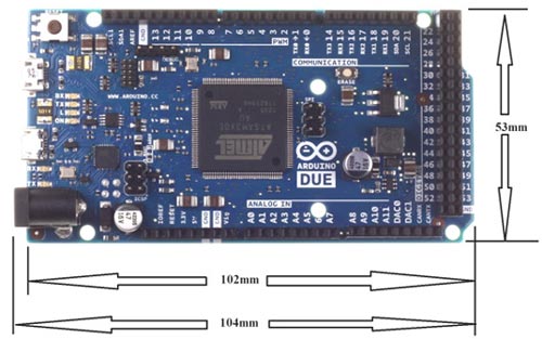
2D-Model and Dimensions