2N3053 General Purpose NPN Transistor
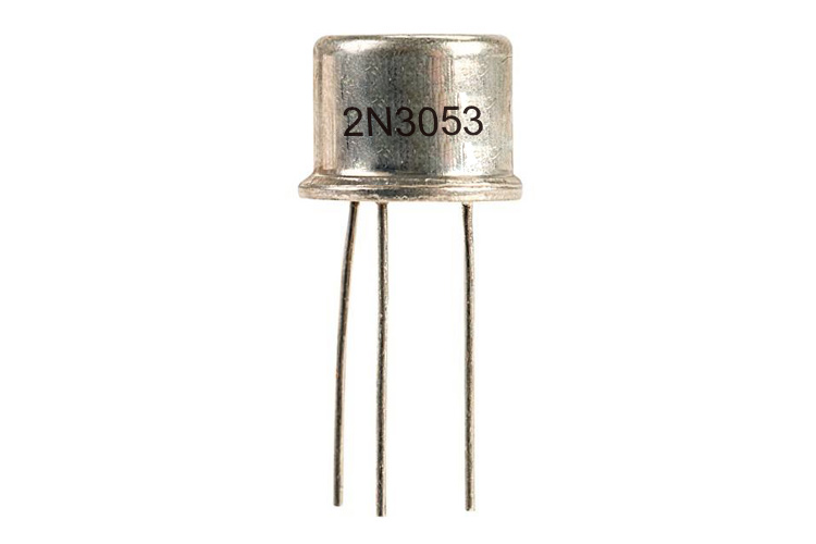
The 2N3053 is a Silicon NPN transistor in a TO-39 metal can package. This type of case is designed primarily for amplifier and switching applications. This device features high breakdown voltage, low leakage current, low capacity, and beta useful over an extremely wide current range.
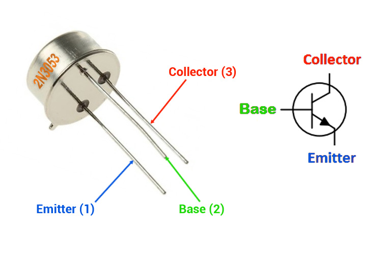
2N3053 Transistor Pinout Configuration
|
Pin Number |
Pin Name |
Description |
|
1 |
Emitter |
Electrons emitted from the emitter into the first PN junction |
|
2 |
Base |
Controls the biasing of the transistor |
|
3 |
Collector |
Electrons Emitted from Emitter, Collected by the Collector |
Basic Overview and Features of 2N3053 Transistor
- Bi-Polar NPN Transistor
- DC Current Gain (hFE) is 50 maximum
- Continuous Collector current (IC) is 700mA
- Emitter Base Voltage (VBE) is 5V
- Base Current (IB) is 15mA maximum
- Maximum Collector-Base Voltage |Vcb|: 80 V
- Collector Dissipation: 5 W
- Transition Frequency: >100 MHz
- Operating and Storage Junction Temperature Range -65 to +200 °C
- Collector Capacitance <15pF
- Input Capacitance <80pF
- Available in TO-39 Metal Can Package
Note: Complete Technical Details can be found in the 2N3053 datasheet given at the end of this page.
2N3053 Equivalent Transistor
BC108, SL100, 2N2219, 2N5210, 2N5321, BC140, BC141, BC440, BC441
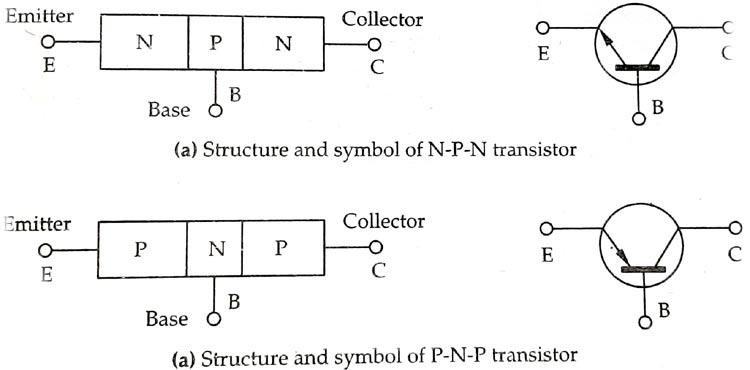
Basic Working of a Transistor
The 2N3053 Transistor is a general-purpose N-P-N transistor, A junction transistor is a sandwiched construction between two layers of N-type material or P-type material, depending upon the construction transistors are divided into two categories NPN transistor and PNP transistor, which are shown below. transistors are made up of silicon or germanium, depending upon the application, the applicant has to choose an appropriate one.
General Description of 2N3053 Transistor
2N3053 is an NPN transistor so when no power is applied to the base, the collector and emitter will be left open (Reverse Biased). Until positive voltage is applied to the base of the transistor, when there is a positive voltage, a small amount of current starts to flow from base to emitter and the transistor reaches its on state. The max gain of this transistor is 50, which determines the amplification factor of the device. The maximum base current is limited to 15mA for this device, more than that and there is a good chance it could damage the device. The collector emitter current for this device is 700mA more than 700mA could damage the device. This is a 5W rated transistor and can be used for many different applications.
When this transistor is in biased condition, then it can allow a maximum current of 700mA with 5W power capacity across CE(Collector Emitter) Junction, this state of the transistor is called the saturation state, and driving a load that consumes more current than 700mA may damage the device. As you already may know a transistor is a current controlled device so when the base current is removed the transistor will migrate to its off state, in this stage the transistor is working in its Cut-off Region so no current flows through the base emitter junction.
How to use 2N3053 Transistor
Transistors are current controlled devices, meaning they can be turned on or off by supplying required base current, for the 2N3053 Transistor it is 15mA. 2N3053 is an NPN transistor that means it will be left open when no current is applied to its base, but when we apply a base voltage a small amount of base current flows through the transistor, and the transistor turns on. The simulated circuit below shows how this transistor behaves when a base current is applied to the and when no current is provided to the base.
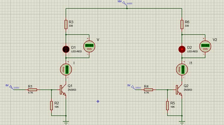
When we turn on the transistor by supplying a required current to the base of the transistor, it will remain on unless the voltage at the base of the transistor reaches zero. The base of the transistor cannot be left floating otherwise there could be false triggering to the transistor which may lead to issues in the circuit. To resolve the issue, we need to add pulldown resistors. For example, a 10K resistor is used to pull down the base of the transistor.
Applications
BC108 Transistor is a very versatile device, its high frequency range and large bandwidth make it suitable for many different applications.
- LED dimmers or flashers
- Switching Applications
- Preamplifier for Power Amplifier
- High frequency switching
- Modulator and Demodulator for RF freque
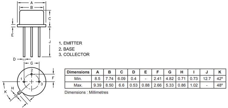
2D Model and Dimensions
If you are designing a PCB or Perf board with this component then the following picture from the Datasheet will be useful to know its package type and dimensions.