2.4” TFT LCD Module
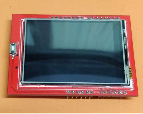
A 2.4” TFT LCD module consists of a bright backlight (4 white LEDs) and a colourful 240X320 pixels display. It also features individual RGB pixel control giving a much better resolution than the black and white displays. A resistive touch screen comes pre-installed with the module as a bonus and hence you can easily detect your finger presses anywhere on the screen.
Features and Specifications
- 2.4” TFT LCD with Touch screen
- Pixels: 240X320
- Operating Voltage: 3.3V
- Operating Mode: SPI and 8-bit mode
- Interface IC: 74LVX245
- SD card option available for displaying bitmap images
- Can be easily interfaced with Arduino (Library available)
Alternative Display Modules
16×2 LCD Display, Dot Matrix LED Display, 7-Segment LED Display, Nokia 5110 Display, TFT LCD Screen Display
TFT LCD Module Pinout
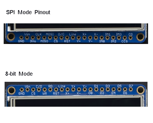
SPI Mode Pinout
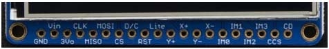
This mode is generally used when speed is not the priority. It is very easy to port to different microcontrollers. In SPI mode, microSD card socket can be used on the same SPI bus. It sends one bit at a time, hence it is slower than the 8-bit mode which sends all the bits in parallel.
|
PIN name |
Description |
|
GND |
Power and signal ground pin. |
|
Vin (3.5V) |
Power pin that can be connected to 3-5VDC. It comes with reverse polarity protection. |
|
Vout |
The 3.3V output from the onboard regulator. |
|
CLK |
It is the SPI clock input pin. |
|
MISO |
This is the SPI Master in Slave Out pin which is mostly used by the SD card and also for debugging TFT. |
|
MOSO |
This is the SPI Master Out Slave Out pin which is used to send data to SD card or the TFT. |
|
CS |
SPI chip select pin |
|
D/C |
SPI data or command selector pin. |
|
RST |
The TFT comes with an auto-reset circuit which gets active on every breakout. However, a user can reset the module using this pin also, in case setup is not resetting clean. |
|
Lite |
It is the PWM input to control the backlight. By default, it is pulled high which means backlight is ON. The PWM can be done on any frequency and it can also be pulled down to turn off the backlight. |
|
IM3 IM2 IM1 IM0 |
These are the interface control set pins. A user can break these out for advanced use. |
|
Card CS / CCS |
SD card chip select pin is used to read from SD card. |
|
Card Detect/CD |
The SD card detects pin is in the float state when SD card is inserted and connected to Ground when there is no SD card. |
8-bit Mode
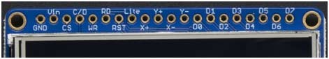
This mode requires a lot of pins (around 12) but provides a lot of speed because it sends 8-bits at a time.
|
PIN Name |
Description |
|
GND |
Power and signal Ground pin |
|
Vin(3.5V) |
Power pin that can be connected to 3-5VDC. It comes with reverse polarity protection. |
|
CS |
8-bit TFT chip select pin which is also tied to SPI mode CS pin. |
|
C/D |
TFT 8-bit data or command selector pin. It is not similar to the SPI D/C pin. However, it is similar to SPI CLK pin. |
|
WR |
TFT 8-bit write strobe pin which is also connected to SPI D/C pin. |
|
RD |
It is read strobe pin for 8-bit TFT. It is used only in the case when a user needs to read from the display. |
|
RST |
The TFT comes with an auto-reset circuit which gets active on every breakout. However, a user can reset the module using this pin also, in case setup is not resetting clean. |
|
Lite |
It is similar to SPI Lite pin. |
|
D0 – D7 |
These pins are used to send the 8-bit parallel data. D0 is the least significant bit while D7 is the most significant one. |
Resistive Touch Pins – Y+, X+, Y-, and X- are the 4 resistive touch pins which require analog pins to read and determine touch pins. Their overlay is fixed at the top of the module which makes them electrically separate from the TFT. They can be used is 8-bit as well as SPI mode.
How to use 2.4” TFT Module
The 2.4” TFT LCD module supports many modes. However, two of them are very popular among users – “SPI mode” and “8-bit mode”. The display contains pins on both sides required for a mode and a user can switch easily between them by simply rewiring the display. It should be noted that only one mode can be used at a time.
The 74LVX245 chip is responsible for interfacing the display with MCU/MPU; it provides fast level shifting so that the user can work on both the logic levels. All the pins are 3.5V logic level compatible. However, if there is an output, the level goes at 3.3V.
Where is 2.4” TFT LCD Module used?
A 2.4” TFT module has a very flexible usage. It is compatible with all your DIY projects where you want to add a bright, colourful, and touchscreen enabled display.
This module can be used in a variety of applications including but not limited to –
- Smartphone
- Point of Sale machine
- Navigation systems
- Gaming consoles
- Touchscreen calculators
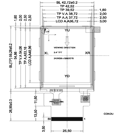
2-D Model and Dimensions